Dust removing method of surface mine dumping plough

A soil dumper and mining technology, which is applied in the field of dust removal, can solve the problems of large unloading drop, secondary pollution, and single dust removal method of the soil dumper, and achieve the effect of suppressing secondary dust and dust

Active Publication Date: 2018-05-18
TAIYUAN IRON & STEEL GROUP +1
View PDF8 Cites 0 Cited by
  • Summary
  • Abstract
  • Description
  • Claims
  • Application Information

AI Technical Summary

Problems solved by technology

[0002] At present, domestic and foreign open-pit mine dump sites use a single dust removal method, mainly spraying dust removal at the material nozzle and spraying dust removal at the head of the discharge arm.
Its main disadvantage is that the water consumption is not easy to control: when there is a lot of water, it is easy to cause the belt to deviate, slip, and the material nozzle is blocked; when the water is small, the dust is large, and the dust removal effect is poor.
[0003] The hourly processing capacity of Yuanjiacun iron ore tape-discharging soil-discharging machine of Taiyuan Iron and Steel Co., Ltd. reaches 8500-10000t / h. The particle size distribution of the material is relatively broad, which contains a large amount of dust that is easily lifted by the wind and floats around under the action of the wind to cause secondary pollution. It is a difficult problem to fully capture the raised dust

Method used


Image

  • Dust removing method of surface mine dumping plough
  • Dust removing method of surface mine dumping plough

Examples


Embodiment

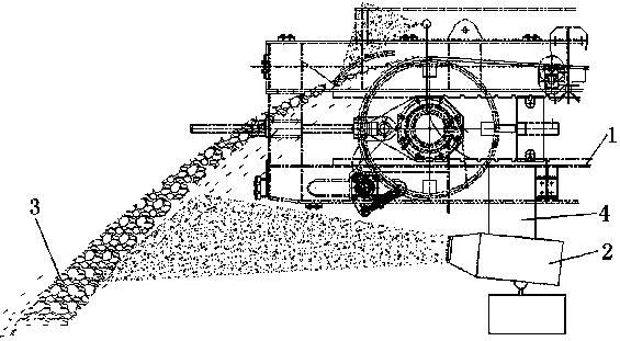
[0029] Such as Figure 1~2 As shown, the present invention adopts the dust removal equipment of a soil dumper to remove dust, and a dust removal method for a soil dumper in an open-pit mine adopts the mode of combining the spray dust removal method and the spray dust removal method. The lower part is equipped with a dust-removing air-supply sprayer 2, and the dust-removing air-supply sprayer 2 is installed at the lower part of the discharge arm 1 at a horizontal distance of 20 meters from the blanking point 3. Since the discharge arm 1 can move up and down, left and right, its load-bearing part is at a distance of 20 meters. 20 meters from the blanking point, it is suitable to install the fixed frame 4 of the dust removal air-supply sprayer; the spray dust removal method is to install the nozzle 5 on the head of the discharge arm 1, and the nozzle 5 is connected to the dust removal water pipe.

[0030] figure 1 The structure of the dust removal device of the soil dumper is sh...


PUM

PropertyMeasurementUnit
Heightaaaaaaaaaa
Lengthaaaaaaaaaa

Abstract

The invention discloses a dust removing method of a surface mine dumping plough. A mode that a mist-spraying dust removing method is combined with a spraying dust removing method is adopted. Accordingto the mist-spraying dust removing method, a dust removing air-assisted mist-spraying machine is mounted at the lower part of a discharging arm, and the dust removing air-assisted mist-spraying machine is mounted at the position, away from a material falling point by the 20-meter horizontal distance, of the lower part of the discharging arm. According to the spraying dust removing method, a nozzle is mounted at the head part of the discharging arm, and the nozzle is connected with a dust removing water pipeline. According to the dust removing method of the surface mine dumping plough, the mode that mist-spraying dust removing is combined with spraying dust removing is adopted and applied to a dust removing system of the surface mine dumping plough, spraying dust removing is used for discharging dust removing of the head part, the mist-spraying machine at the lower part of the discharging arm is mounted at the fixed position so as to ensure the facts that the mist-spraying distance isfixed relatively and the mist-spraying machine does not need to be moved and arranged frequently due to moving of the discharging arm, the dust removing method can play a better inhibiting effect on secondary flying dust generated after discharging of the dumping plough, and the practical effect is obvious.

Description

technical field [0001] The invention relates to a dust removal method for an open-pit mine dumper, in particular to a dust removal method when the dumper is in operation, and belongs to the technical field of dust removal. Background technique [0002] At present, domestic and foreign open-pit mine dump sites use a single dust removal method, mainly spraying dust removal at the material nozzle and spraying dust removal at the head of the discharge arm. Its main disadvantage is that the water consumption is not easy to control: when there is a lot of water, it is easy to cause the belt to deviate, slip and block the material; when the water is small, the dust is large and the dust removal effect is poor. [0003] The hourly processing capacity of Yuanjiacun iron ore tape-discharging soil-discharging machine of Taiyuan Iron and Steel Co., Ltd. reaches 8500-10000t / h. The particle size distribution of the material is relatively wide, and it contains a large amount of dust that ...

Claims


Application Information

Patent Timeline
IPC IPC(8): E21C47/00B01D51/02B01D47/06
CPCB01D47/06B01D51/02E21C47/00
Inventor 王永章庞俊文田巨明马跃岭冯文青张斐
Owner TAIYUAN IRON & STEEL GROUP
Why Eureka
Try Eureka