Flood prevention method for water conservancy project

A technology for water conservancy projects and square plates, applied in water conservancy projects, marine engineering, embankments, etc., can solve the problems of unstable connection of flood control boxes, easy to produce huge impact, poor resistance of flood control walls, etc., to increase the scope of application and reduce friction. force, ensure the effect of safety

Inactive Publication Date: 2021-09-24
刘强
View PDF0 Cites 0 Cited by
  • Summary
  • Abstract
  • Description
  • Claims
  • Application Information

AI Technical Summary

Problems solved by technology

[0004] Aiming at the deficiencies of the prior art, the present invention provides a flood control method for water conservancy projects, which solves the problem that the existing flood control boxes are not firmly connected to each other, resulting in poor overall resistance of the flood control wall. When blocking the flood, the energy of the flood is very large. It is easy to produce a huge impact, causing the flood control box to be knocked down and scattered, and the consequences are very serious.

Method used


Image

  • Flood prevention method for water conservancy project
  • Flood prevention method for water conservancy project
  • Flood prevention method for water conservancy project

Examples


Embodiment 1

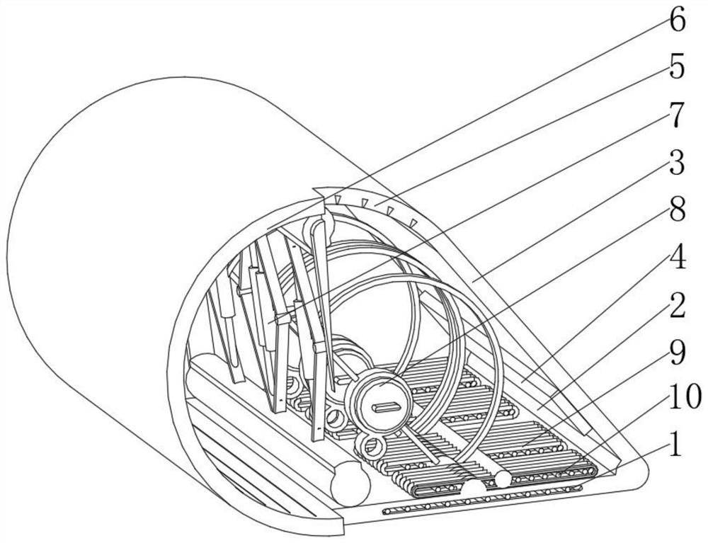
[0044] see Figure 1-5 , the present invention provides a technical solution: a flood control equipment for water conservancy projects, specifically comprising:

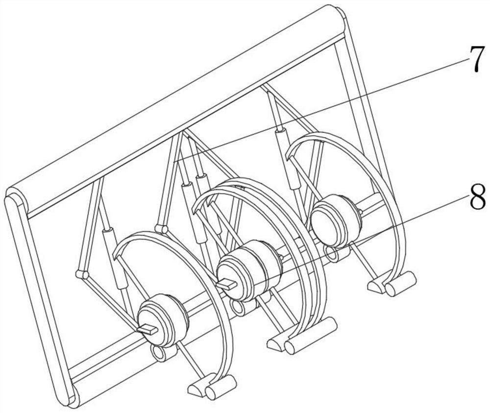
[0045] Base plate 1, the base plate 1 has a square plate body, and a shaft head column 2 installed on the left outer wall of the square plate body, and a cutoff plate 3 installed on the top of the shaft head column 2, characterized in that: and installed on the cutoff plate 3 The permanent magnet 4 near the bottom of the base plate 1, and the spliced ​​magnetic ring plate 5 installed on the top of the cut-off plate 3, and the sealing strips 6 installed on the front and back of the spliced ​​magnetic ring plate 5, and installed on the spliced ​​magnetic ring The lifting device 7 on the top of the inner surface of the plate 5, and the auxiliary device 8 installed on the side of the lifting device 7 near the shaft head column 2, and the electromagnetic coil 9 installed on the top of the square plate body and between the...

Embodiment 2

[0059] see Figure 1-5 On the basis of Embodiment 1, the present invention provides a technical solution: a flood control method for water conservancy projects, comprising the following steps,

[0060] Step 1: Move the position of the net rod 14 along the track groove 13, so that the angle of the rotating plate 15 is adjusted around the positioning axis 16, so that it is in the same direction as the water flow;

[0061] Step 2: Place the whole device in the flood-proof position, fix the position by using the friction between the rotating plate 15 and the ground and its own gravity, and rotate the winding rod 85 so that the winding rod 85 rotates on the inner surface of the lock ring plate 86 to adjust the traction the length of the cord 84;

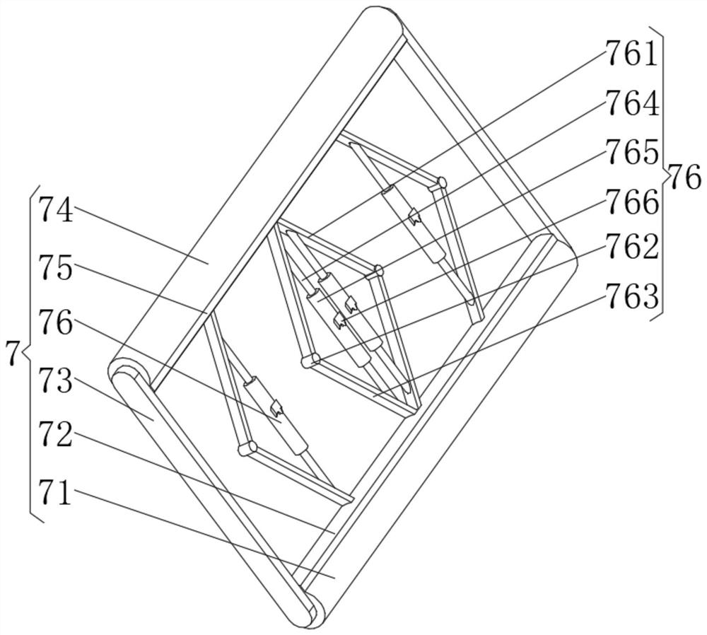
[0062] Step 3: After step 2 is performed, turn the screw barrel 765 and adjust the distance between the studs 764 by threaded connection, so as to adjust the height between the top support plate 761 and the bottom support plate 763, and ...


PUM


Abstract

The invention discloses flood prevention equipment for a water conservancy project. The flood prevention equipment specifically comprises a base plate and an intercepting plate mounted at the top of a shaft head column. The flood prevention equipment is characterized by further comprising a permanent magnet mounted at the bottom of the side, close to the base plate, of the intercepting plate, a splicing magnetic ring plate mounted at the top of the intercepting plate, sealing strip plates mounted on the front face and the back face of the splicing magnetic ring plate, a lifting device mounted at the top of the inner surface of the splicing magnetic ring plate, auxiliary devices mounted on the side, close to the shaft head column, of the lifting device, an electromagnetic coil mounted at the top of a square plate body and located between the auxiliary devices, and a hexagonal iron core mounted in an inner cavity of the electromagnetic coil. The invention relates to the technical field of water conservancy. By adjusting the angle of a rotating plate, the rotating plate is made to be in the same direction as the flowing direction of water flow and abut against the ground, the impact force of the water flow is guided into the ground, the counter-acting force for offsetting is formed, and the overall mounting position of the equipment is stabilized.

Description

technical field [0001] The invention relates to the technical field of water conservancy, in particular to a flood control method for water conservancy projects. Background technique [0002] In flood control, sandbags are usually piled up to form a flood control wall to block floods. However, in the prior art, after the sandbags are superimposed, they are easy to be washed down. At the same time, in this way, once the impact of the flood increases, it will easily be washed away. In addition, the existing flood control boxes are not connected firmly to each other, which leads to poor overall resistance of the flood control wall. When blocking the flood, the energy of the flood is very large, and it is easy to generate a huge impact, causing the flood control box to be washed down and scattered, and the consequences are very serious. serious. Contents of the invention [0003] (1) Solved technical problems [0004] Aiming at the deficiencies of the prior art, the present...

Claims


Application Information

Patent Timeline
Patent Type & Authority Applications(China)
IPC IPC(8): E02B3/10E02B3/16E02B8/06H01F7/02H01F5/00
CPCE02B3/106E02B3/16E02B8/06H01F7/02H01F5/00
Inventor 刘强
Owner 刘强
Why Eureka
Try Eureka