Energy-saving operation monitoring system for screw air compressor

An operation monitoring and air compressor technology, applied in mechanical equipment, machines/engines, liquid fuel engines, etc., can solve the problems affecting users' observation and recording of operating values, electric shock, and water mist generation, so as to avoid injury, Improve the contact area and facilitate precise control

Pending Publication Date: 2021-09-24
江苏气老板节能技术有限公司
View PDF4 Cites 0 Cited by
  • Summary
  • Abstract
  • Description
  • Claims
  • Application Information

AI Technical Summary

Problems solved by technology

[0003] In order to solve the problems raised in the above-mentioned background technology, the object of the present invention is to provide an energy-saving operation monitoring system for screw air compressors, which has the advantage of being convenient for cleaning water mist, and solves the problem that the surface of the existing operation monitoring device will be damaged during use. The water mist generated by the temperature difference has seriously affected the user's observation and recording of the operating value, and the user may have an electric shock problem during the process of wiping the water mist

Method used


Image

  • Energy-saving operation monitoring system for screw air compressor
  • Energy-saving operation monitoring system for screw air compressor
  • Energy-saving operation monitoring system for screw air compressor

Examples


Embodiment Construction

[0030] The following will clearly and completely describe the technical solutions in the embodiments of the present invention with reference to the accompanying drawings in the embodiments of the present invention. Obviously, the described embodiments are only some, not all, embodiments of the present invention. Based on the embodiments of the present invention, all other embodiments obtained by persons of ordinary skill in the art without making creative efforts belong to the protection scope of the present invention.

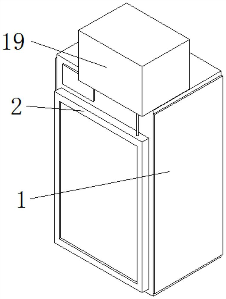
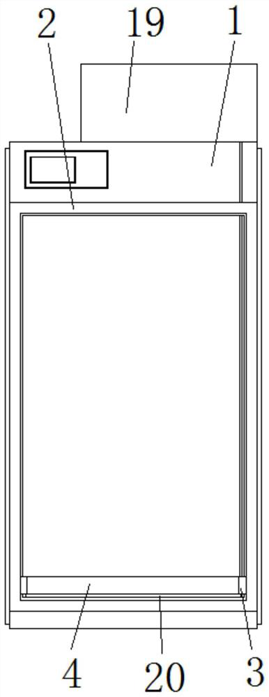
[0031] Such as Figure 1 to Figure 6 As shown, a screw air compressor energy-saving operation monitoring system provided by the present invention includes a monitoring box 1;

[0032] The transparent protective door 2 that is installed on the front side of the monitoring box 1;

[0033] The back of the protective door 2 is provided with a connecting plate 3, and the front of the connecting plate 3 is fixedly connected with a sponge block 4, and the side of th...


PUM


Abstract

The invention discloses an energy-saving operation monitoring system for a screw air compressor. The energy-saving operation monitoring system comprises a monitoring box and a transparent protective door installed on the front face of the monitoring box, wherein a connecting plate is arranged on the back face of the protective door, a sponge block is fixedly connected to the front face of the connecting plate, the side, away from the connecting plate, of the sponge block is in contact with the surface of the protective door, a transmission motor is fixedly connected to the top of the monitoring box, and a connecting rod is fixedly connected to the output end of the transmission motor. According to the energy-saving operation monitoring system, a winding wheel is driven to rotate through the transmission motor and the connecting rod, the winding wheel winds a steel cable and pulls the connecting plate to ascend, and the connecting plate wipes the protective door through the sponge block in the moving process, so that the effect of removing water mist is achieved, and the problems that in the use process of an existing operation monitoring device, water mist can be generated on the surface of the device due to temperature difference, a user is seriously affected in observing and recording operation numerical values, and the user is likely to get an electric shock in the process of wiping off the water mist are solved.

Description

technical field [0001] The invention relates to the technical field of air compressors, in particular to an energy-saving operation monitoring system for screw air compressors. Background technique [0002] In order to avoid accidents, the air compressor needs to run an energy-saving monitoring system to monitor the operating status of the monitoring device in real time during operation. However, the surface of the existing operation monitoring device will generate water mist due to temperature differences during use. It has seriously affected the user's observation and recording of the operating values, and the user may also get an electric shock in the process of wiping the water mist. Contents of the invention [0003] In order to solve the problems raised in the above-mentioned background technology, the purpose of the present invention is to provide an energy-saving operation monitoring system for screw air compressors, which has the advantage of being convenient for ...

Claims


Application Information

Patent Timeline
Patent Type & Authority Applications(China)
IPC IPC(8): F04C18/16F04C28/28F04C29/00
CPCF04C18/16F04C28/28F04C29/00
Inventor 高雄发
Owner 江苏气老板节能技术有限公司
Why Eureka
Try Eureka