Method and system for modifying fuel gas nozzle based on fuel oil nozzle

A technology of gas nozzles and fuel nozzles, which is applied in the direction of combustion methods, combustion chambers, combustion equipment, etc., and can solve the problem that gas fuel cannot be effectively injected into the combustion area, etc.

Pending Publication Date: 2021-09-24
AECC AVIATION POWER CO LTD
View PDF3 Cites 0 Cited by
  • Summary
  • Abstract
  • Description
  • Claims
  • Application Information

AI Technical Summary

Problems solved by technology

[0003] The purpose of the present invention is to overcome the disadvantages of the above-mentioned prior art that the nozzles of the gas turbine are all liquid fue...

Method used


Image

  • Method and system for modifying fuel gas nozzle based on fuel oil nozzle
  • Method and system for modifying fuel gas nozzle based on fuel oil nozzle
  • Method and system for modifying fuel gas nozzle based on fuel oil nozzle

Examples


Embodiment 1

[0038] A method for modifying a gas nozzle based on a fuel nozzle, comprising the steps of:

[0039] Step 1) Select a certain working condition as the design point of the gas nozzle, obtain the pressure drop of the gas nozzle, and calculate the gas injection velocity;

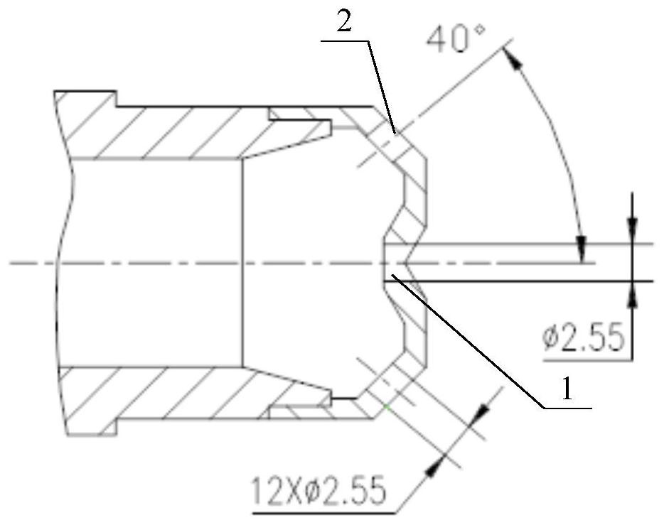
[0040] Step 2) based on the size of the fuel nozzle and the gas injection velocity, obtain the total area of ​​the nozzles on the gas nozzle, and calculate the number and diameter of the nozzles;

[0041] The process of obtaining the total area of ​​the nozzle is:

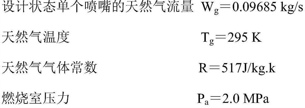
[0042] Calculate the gas density based on the gas temperature, gas constant and combustion chamber pressure;

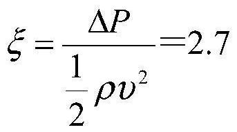
[0043] According to the gas density, nozzle form and wall thickness, the flow resistance coefficient of the nozzle is obtained;

[0044] Based on the pressure drop of the gas nozzle, the gas injection velocity and the flow resistance coefficient of the nozzle, the total area of ​​the nozzle is calculated.

[0045] Step 3) Obtain the layo...

Embodiment 2

[0049] Except for the following content, all the other contents are the same as in Example 1.

[0050] The calculation process of the gas injection velocity is as follows: the gas flow rate is obtained based on the pressure drop of the gas nozzle, and the gas injection velocity is obtained by combining the gas temperature, the gas constant of the gas and the pressure of the combustion chamber.

[0051] The calculation process of the number and diameter of the nozzles is: based on the total area of ​​the nozzles and the nozzle diameter of the fuel nozzle, the area and the number of the individual nozzles are calculated; based on the number of the nozzles and the area of ​​the individual nozzles, the diameter of the individual nozzles is calculated.

Embodiment 3

[0053] A method for modifying a gas nozzle based on a fuel nozzle, comprising the steps of:

[0054] Step 1): For the design of the gas nozzle, the 1.0 working condition is selected as the nozzle design point. The design should ensure that the heat release per unit time when using natural gas is the same as when using diesel; ensure that the number of nozzles and installation dimensions remain unchanged.

[0055] According to the design data and actual use experience of the gas nozzle, the important design parameter is the nozzle pressure drop. The recommended nozzle pressure drop is about 10% of the gas supply pressure to ensure stable and efficient combustion and meet the requirements of outlet temperature distribution. At the same time, consider service life. If the pressure drop is too high, it will easily lead to unstable operation of the nozzle, and it is easy to spray to the near wall, resulting in excessive wall temperature; if the pressure drop is too low, the mixing...


PUM


Abstract

The invention discloses a method and system for modifying a fuel gas nozzle based on a fuel oil nozzle, belongs to the field of engine design. The method comprises the steps: determining a main geometric dimension of the fuel gas nozzle according to performance parameters required by design points; and after a gas pressure difference is determined, selecting the nozzle form to give a flow resistance coefficient and an injection speed, and then calculating a total area and a size of a single nozzle according to a gas flow. The power of the modified gas turbine is equal to that of an original fuel nozzle, the efficiency of the modified gas turbine is not lower than that of a prototype machine, the performance of a modified combustion chamber is consistent with that of the prototype machine, such as combustion efficiency, outlet temperature field and the like, and after the nozzle is modified, the heat release amount of fuel in unit time of the fuel nozzle is consistent with that of fuel in unit time of the gas nozzle. The gas nozzle and the fuel oil nozzle are consistent in outlet pressure, close in injection speed and identical in injection angle. Therefore, when the number and the installation size of the nozzles are not changed, the heat release amount of natural gas is the same as that of the fuel oil.

Description

technical field [0001] The invention belongs to the field of engine design and relates to a method and system for modifying a gas nozzle based on a fuel nozzle. Background technique [0002] With the increasing demand for gas turbines in the industrial market, considering the requirements of environmental protection, gas turbines fueled by clean energy natural gas have broad application prospects. The nozzle is an important part of the combustion chamber of a gas turbine, and it is also an important item in the design of the combustion chamber. Its performance has a great influence on the combustion process. The fuel is injected into the combustion chamber through the nozzle and mixed with the incoming air to form a combustible mixture to ensure stable combustion in the combustion chamber. The remodeled industrial gas turbine uses natural gas as fuel, and the fuel is changed from liquid to gas. The corresponding nozzles also need to be redesigned, so that the designed new n...

Claims


Application Information

Patent Timeline
IPC IPC(8): F23R3/38
CPCF23R3/38
Inventor 彭春梅沈辰李鹏梁明莉秦金虎王建辉王勇
Owner AECC AVIATION POWER CO LTD
Why Eureka
Try Eureka