Optical lens, camera module, electronic equipment and automobile

An optical lens and camera module technology, which is applied in the fields of electronic equipment and automobiles, optical lenses, and camera modules, can solve the problems of small shooting angle of optical lens, difficult to meet shooting and clear imaging, and low resolution, so as to improve the resolution. rate and imaging clarity, meeting high-definition imaging requirements, and expanding the range of viewing angles

Active Publication Date: 2021-09-24
JIANGXI JINGCHAO OPTICAL CO LTD
View PDF7 Cites 4 Cited by
  • Summary
  • Abstract
  • Description
  • Claims
  • Application Information

AI Technical Summary

Problems solved by technology

In related technologies, under the design trend of thin, light and miniaturized optical lenses, the shooting angle of the optical lens is small, the resolution is low, it is difficult to meet the shooting and clear imaging of a wide range of angles, and thus cannot meet the shooting requirements of a large field of view

Method used


Image

  • Optical lens, camera module, electronic equipment and automobile
  • Optical lens, camera module, electronic equipment and automobile
  • Optical lens, camera module, electronic equipment and automobile

Examples


no. 1 example

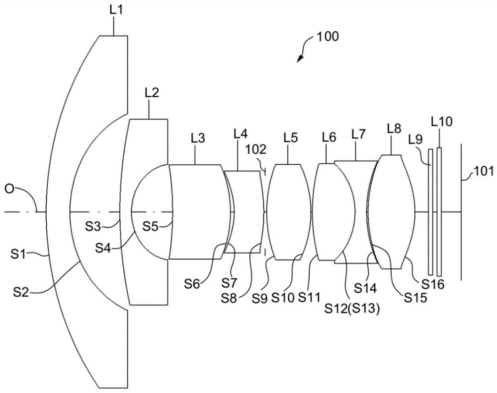
[0090] The structural diagram of the optical lens 100 disclosed in the first embodiment of the present application is as follows figure 1 As shown, the optical lens 100 includes a first lens L1, a second lens L2, a third lens L3, a fourth lens L4, a diaphragm 102, a fifth lens L5, and a first lens L1 arranged in sequence along the optical axis O from the object side to the image side. Six lenses L6, seventh lens L7, eighth lens L8, filter L9 and cover glass L10. Wherein, regarding the refractive power of the first lens L1, the second lens L2, the third lens L3, the fourth lens L4, the fifth lens L5, the sixth lens L6, the seventh lens L7 and the eighth lens L8, please refer to the above specific implementation way, and will not be repeated here.

[0091] Further, the object side S1 and the image side S2 of the first lens L1 are respectively convex and concave at the near optical axis O. The object side S3 and the image side S4 of the second lens L2 are respectively convex an...

no. 2 example

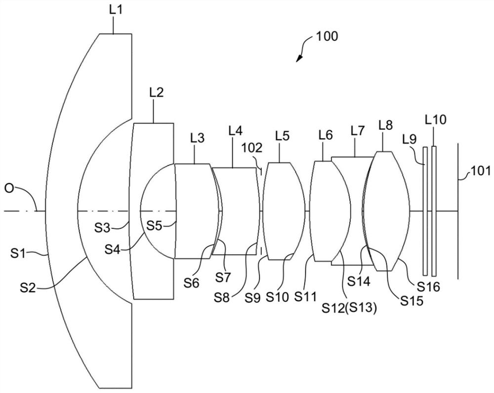
[0107] Please refer to image 3 , image 3 It is a schematic structural diagram of the optical lens 100 according to the second embodiment of the present application. The optical lens 100 includes a first lens L1, a second lens L2, a third lens L3, a fourth lens L4, a diaphragm 102, a fifth lens L5, and a sixth lens L6 arranged in sequence from the object side to the image side along the optical axis O , the seventh lens L7, the eighth lens L8, the filter L9 and the protective glass L10. Wherein, regarding the refractive power and materials of the first lens L1, the second lens L2, the third lens L3, the fourth lens L4, the fifth lens L5, the sixth lens L6, the seventh lens L7 and the eighth lens L8, please refer to the above-mentioned As described in the specific implementation manner, details will not be repeated here.

[0108] Further, for the surface shapes of the first lens L1, the second lens L2, the third lens L3, the fourth lens L4, the fifth lens L5, the sixth lens...

no. 3 example

[0122] Please refer to Figure 5 , Figure 5A schematic structural diagram of the optical lens 100 according to the third embodiment of the present application is shown. The optical lens 100 includes a first lens L1, a second lens L2, a third lens L3, a fourth lens L4, a diaphragm 102, a fifth lens L5, and a sixth lens L6 arranged in sequence from the object side to the image side along the optical axis O , the seventh lens L7, the eighth lens L8, the filter L9 and the protective glass L10. Wherein, regarding the refractive power and materials of the first lens L1, the second lens L2, the third lens L3, the fourth lens L4, the fifth lens L5, the sixth lens L6, the seventh lens L7 and the eighth lens L8, please refer to the above-mentioned As described in the specific implementation manner, details will not be repeated here.

[0123] Further, for the surface shapes of the first lens L1, the second lens L2, the third lens L3, the fourth lens L4, the fifth lens L5, the sixth l...


PUM


Abstract

The invention discloses an optical lens, a camera module, electronic equipment and an automobile. The optical lens comprises a first lens, a second lens, a third lens, a fourth lens, a fifth lens, a sixth lens, a seventh lens and an eighth lens which are sequentially arranged from an object side to an image side along an optical axis, wherein the first lens has negative refractive power; the second lens has negative refractive power; the third lens has positive refractive power; the fourth lens has negative refractive power; the fifth lens has positive refractive power, the sixth lens has positive refractive power, the seventh lens has negative refractive power, and the eighth lens has positive refractive power; the optical lens meets the following relation: -6 < f1 / f <-4, f1 is the focal length of the first lens, and f is the effective focal length of the optical lens. According to the optical lens, the camera module, the electronic equipment and the automobile provided by the invention, light rays emitted into the optical lens at a large angle can be grasped while the light, thin and small-sized design is met, the super-large-angle shooting requirement can be met, and high-pixel imaging can be realized.

Description

technical field [0001] The invention relates to the technical field of optical imaging, in particular to an optical lens, a camera module, electronic equipment and an automobile. Background technique [0002] At present, with the development of camera technology, people have higher and higher requirements for the imaging quality of optical lenses, and at the same time, the structural characteristics of lightness, thinness and miniaturization have gradually become the development trend of optical lenses. In related technologies, under the design trend of thin, light and miniaturized optical lenses, the shooting angle of the optical lens is small, the resolution is low, it is difficult to meet the shooting and clear imaging of a wide range of angles, and thus cannot meet the shooting requirements of a large field of view . Contents of the invention [0003] The embodiment of the invention discloses an optical lens, a camera module, an electronic device and a car, which can ...

Claims


Application Information

Patent Timeline
Patent Type & Authority Applications(China)
IPC IPC(8): G02B13/00G02B13/06G02B13/18G02B7/02G03B30/00
CPCG02B13/0045G02B13/18G02B13/06G02B13/006G02B7/028G03B30/00
Inventor 乐宇明蔡雄宇兰宾利赵迪
Owner JIANGXI JINGCHAO OPTICAL CO LTD
Why Eureka
Try Eureka