
Elevated road lifting access system

A technology for elevated roads and high-speed roads, applied in the field of elevated road access and exit systems, which can solve problems such as high cost, no exit, and long time consumption

Pending Publication Date: 2021-09-28
张成文
View PDF0 Cites 0 Cited by
  • Summary
  • Abstract
  • Description
  • Claims
  • Application Information

AI Technical Summary

Problems solved by technology

Over time, it brings high cost and long time consumption to drivers
In many cases, the expressway often crosses the general road, and there is no exit for various reasons, which brings inconvenience to people's going up and down.

Method used


Image

  • Elevated road lifting access system
  • Elevated road lifting access system
  • Elevated road lifting access system

Examples


Embodiment 1

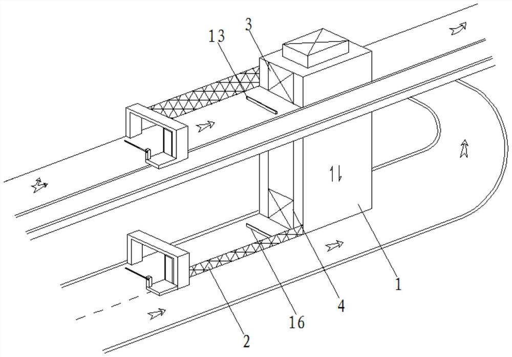
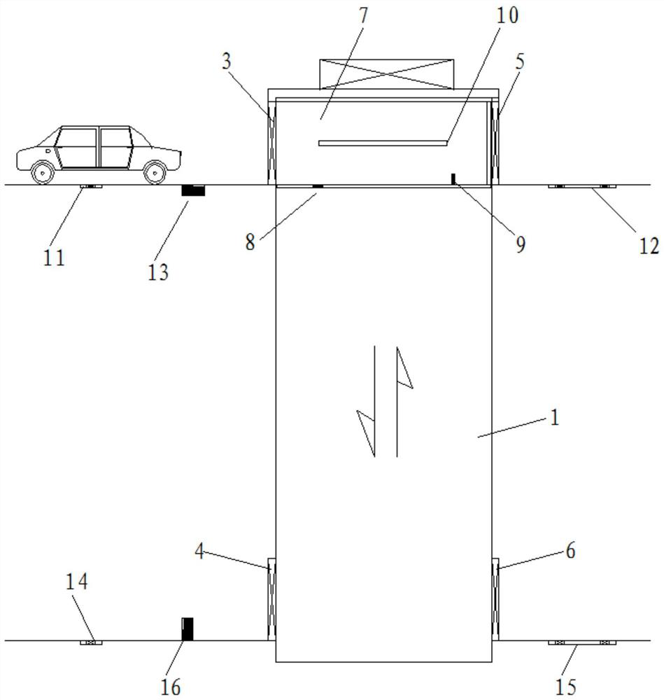
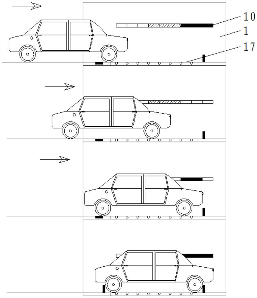
[0028] see figure 1 and figure 2 , an elevated road lifting access system, erected on the basis of a highway, viaduct or elevated road, including an elevator 1, a partition wall 2 and an elevator car 7, the elevator car 7 is movable inside the elevator 1, and the partition wall 2 is arranged on the On both sides of the road in front of the elevator 1, an upper entry door 3 and an upper exit door 5 are respectively provided at the front and rear of the top of the elevator 1, and a lower entry door 4 and a lower exit door 6 are respectively provided at the front and rear of the bottom end of the elevator 1;

[0029] On the road in front of the upper entrance door 3, an upper entry sensor 11 and an upper bumper 13 are arranged successively; on the road behind the upper exit door 5, an upper exit sensor 12 is arranged; A lower running-in sensor 14 and a lower bumper 16 are arranged in sequence, and a lower running-out sensor 15 is arranged on the road behind the lower going out ...

Embodiment 2

[0036] see Figure 11, the elevated road access system described in Embodiment 1 is used to set up on the expressway, and the partition wall is located in the side lane between the toll station and the elevator building, which is used to prevent the adjacent lanes from communicating, and is equipped with car monitoring The entrance is used to determine according to the design parameters of the elevator and monitor overweight, super high, super long and super wide vehicles, which will not be allowed to pass. The toll station increases the functions of controlling vehicles (vehicles accommodated according to design requirements between the toll station and the elevator) and chain elevators.

[0037] The car monitoring gate is linked with the toll station. After the normal vehicle passes the monitoring gate, the green indicator light is on, the gear lever of the toll station is lifted, and the vehicle passes through the toll; after the overrun vehicle passes the monitoring gate,...


PUM


Abstract

The invention discloses an elevated road lifting access system, and belongs to the technical field of road traffic. The system is erected on the basis of a highway, a viaduct or an elevated road and comprises an elevator, a separation wall and an elevator car. The elevator car is movably arranged in the elevator, and the separating walls are arranged on the two sides of a road in front of the elevator. An upper entrance door and an upper exit door are respectively arranged in front of and behind the top end of the elevator; a lower entrance door and a lower exit door are respectively arranged in front of and behind the bottom end of the elevator; and an upper driving-in sensor and an upper bumper are sequentially arranged on the road surface in front of the upper entrance door. The elevated road lifting access system is erected between the highway, the viaduct and the highway below (or above) the viaduct in a crossed or parallel mode so as to facilitate entering and exiting of automobiles, and the elevated road lifting access system serves as an auxiliary access system of an expressway access, brings great convenience to automobile drivers, enables the automobile drivers to have few detour. The system is more time-saving and economic.

Description

technical field [0001] The invention belongs to the technical field of road traffic, and in particular relates to a lift access system for elevated roads. Background technique [0002] In modern society, the highway traffic network extends in all directions; especially expressways, viaducts, and elevated roads can be found everywhere; it brings great convenience for people to travel by car. In the bustling eastern region, traffic is like a web; in the gully-crissed southwest region, expressways (including viaducts, elevated roads) abound; in actual travel, due to geographical constraints and space constraints, there are fewer entrances and exits on and off expressways , detour away at high speed. Over time, it brings high cost and long time consumption to drivers. In many cases, the expressway will cross the general road, and there is no exit for various reasons, which brings inconvenience to people's going up and down. My invention is exactly, in this case, can be at exp...

Claims


Application Information

Patent Timeline
Patent Type & Authority Applications(China)
IPC IPC(8): E01C1/04E01C1/00E01F9/608E01F9/615E01F13/08E01F15/14B66B11/02B66B5/00G01D21/02
CPCE01C1/04E01C1/002E01C1/007E01F13/08E01F9/608E01F9/615E01F15/146B66B11/0226B66B5/0012G01D21/02
Inventor 张成文
Owner 张成文
Learn More