

Precast concrete tubular column steel reinforced concrete beam joint structure and construction method thereof
A technology of steel reinforced concrete and precast concrete, which is applied in the direction of building structure and construction, can solve the problems of lack of protection mechanism of steel reinforced concrete beam, broken and falling of steel reinforced concrete beam, lack of buffer and shock absorption mechanism, etc., so as to improve the connection Stability and anti-vibration buffer capacity, improve load bearing capacity, improve the effect of shock absorption and buffer effect
- Summary
- Abstract
- Description
- Claims
- Application Information
AI Technical Summary
Problems solved by technology
Method used
Image

Examples
Embodiment Construction
[0039] The following will clearly and completely describe the technical solutions in the embodiments of the present invention with reference to the accompanying drawings in the embodiments of the present invention. Obviously, the described embodiments are only some, not all, embodiments of the present invention. Based on the embodiments of the present invention, all other embodiments obtained by persons of ordinary skill in the art without making creative efforts belong to the protection scope of the present invention.
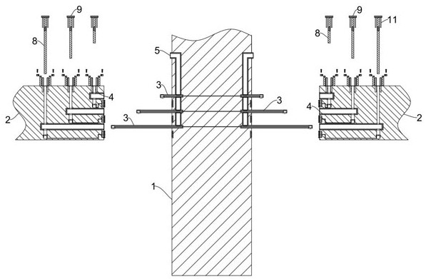
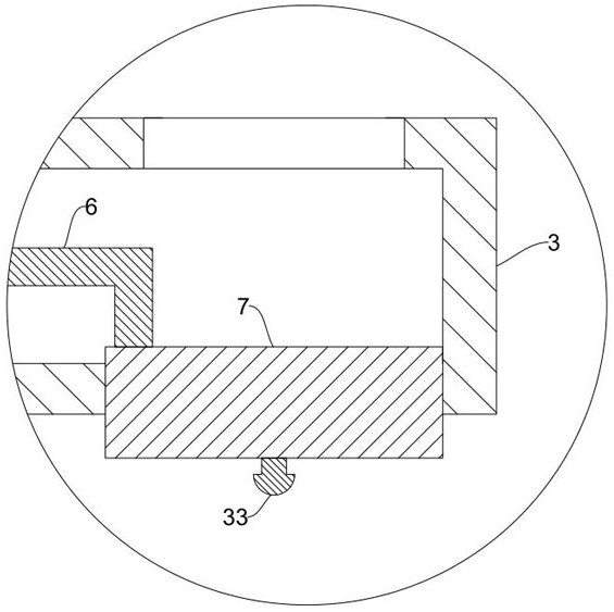
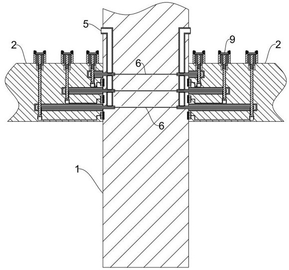
[0040] see Figure 1-9 , the present invention provides a technical solution:
[0041] A prefabricated concrete pipe column steel-reinforced concrete beam node structure, comprising steel-reinforced concrete beams 2 located on both sides of the concrete pipe column 1, first insertion sockets 3 fixedly protruding from both sides of the concrete pipe column 1, and inside the steel-reinforced concrete beam 2 The insertion cylinder 4 for the insertion of the first ...
PUM
 Abstract
Description
Claims
Application Information