Shunt

A shunt and current technology, applied in the direction of instruments, measuring devices, measuring electrical variables, etc., can solve the problems of poor accuracy of test results, waveform distortion, current waveform amplitude error, etc., to reduce the impact, reduce the amplitude error and Effects of waveform distortion and reduction of residual inductance

Pending Publication Date: 2021-09-28
SIEMENS TRANSFORMER GUANGZHOU
View PDF0 Cites 0 Cited by
  • Summary
  • Abstract
  • Description
  • Claims
  • Application Information

AI Technical Summary

Problems solved by technology

[0003] During the lightning impulse test, a large and rapidly changing current will be generated on the coil of the transformer, and the current shunt used for the lightning impulse test of the transformer has a large residual inductance, and the current generated is collected through the shunt , the large residual inductance of the shunt will cause large amplitude errors and waveform distortions in the collected current waveforms, and the current waveforms with large amplitude errors and waveform distortions will affect the judgment of the test results, leading to The result is less accurate

Method used


Image

  • Shunt
  • Shunt
  • Shunt

Examples


Embodiment 1

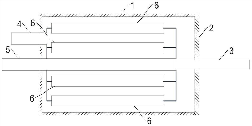
[0061] figure 1 It is a schematic diagram of a flow divider provided in Embodiment 1 of the present application. The shunt provided in the embodiment of the present application is used to sample the current on the transformer winding in the lightning impulse test of the transformer, such as figure 1 As shown, the shunt includes: a housing 1, an end cover 2, an access terminal 3, a ground terminal 4, a measuring terminal 5 and at least three resistors 6;

[0062] The housing 1 is a barrel-shaped structure, and each resistor 6 is arranged in the housing 1;

[0063] Each resistor 6 has the same resistance value, and each resistor 6 is a cylindrical structure;

[0064] The axis of each resistor 6 is parallel to the axis of the housing 1, on a section perpendicular to the axis of the housing 1, each resistor 6 is located on the same circumference, and the distance between adjacent resistors 6 in each resistor 6 equal distance;

[0065] The end cover 2 is connected to the top of...

Embodiment 2

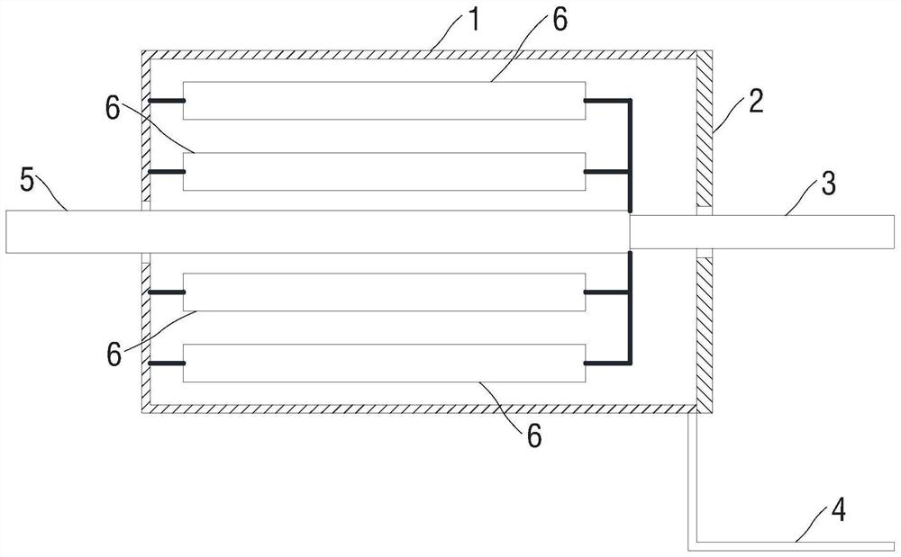
[0075] figure 2 It is a schematic diagram of a shunt provided in Embodiment 2 of the present application, such as figure 2 As shown, the housing 1 is a stainless steel housing, the second end of each resistor 6 is connected to the bottom of the housing 1 , and the first end of the ground terminal 4 is connected to the top of the housing 1 .

[0076] In the embodiment of the present application, the housing 1 is a stainless steel housing, and the second end of each resistor 6 and the grounding terminal 4 are connected to the housing 1, so that the connection between each resistor 6 and the grounding terminal 4 is more convenient, so that The structure of the flow divider is more simplified, so that the flow divider has a smaller volume, and the cost of the flow divider can be reduced. In addition, since each resistor 6 is located in the casing 1, the casing 1 is a conductor, and the casing 1 is grounded through the ground terminal 4, so the casing 1 can play the role of shie...

Embodiment 3

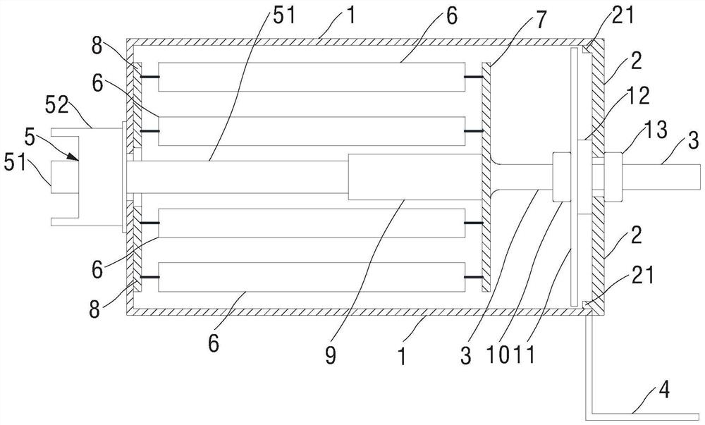
[0084] image 3 It is a schematic diagram of a shunt provided in Embodiment 3 of the present application, Figure 4 It is a schematic diagram of a resistor distribution provided in Embodiment 3 of the present application. exist figure 2 shown on the basis of the shunt, as image 3 and Figure 4 , the shunt also includes a first support plate 7, a second support plate 8 and a plug connector 9;

[0085] Both the first support disc 7 and the second support disc 8 are disc-shaped structures, and the diameters of the first support disc 7 and the second support disc 8 are smaller than the inner diameter of the housing 1;

[0086] The first side of the first support plate 7 is connected to the first end of each resistor 6 respectively, and the second side of the first support plate 7 is connected to the first end of the access terminal 3;

[0087] The first side of the second support plate 8 is in contact with the inner side wall of the bottom of the housing 1, and the second sid...


PUM


Abstract

The invention provides a shunt, which is used for sampling current on a transformer winding in a lightning impulse test of a transformer, and comprises a shell, an end cover, an access end, a grounding end, a measuring end and at least three resistors which have the same resistance value and are of cylindrical structures, all the resistors are located in the cylindrical shell, the axes of all the resistors are parallel to the axis of the shell, all the resistors are located on the same circumference, and the distances between the adjacent resistors are equal; the access end is connected with the first end of each resistor; the grounding end is connected with the second end of each resistor; the measuring end is connected with the first end of each resistor; when the access end is connected with the winding of the transformer, the second end of the grounding end is grounded, and the measuring end is connected with an external oscilloscope, the measuring end sends a voltage signal to the oscilloscope. When the shunt provided by the scheme is used for a lightning impulse test, the amplitude error and waveform distortion of the collected current waveform can be reduced.

Description

technical field [0001] This application relates to the technical field of electrical engineering, in particular to a shunt. Background technique [0002] The transformer running in the power system may be struck by lightning. In order to ensure that the transformer can work normally after being struck by lightning, it is necessary to conduct a lightning impulse test on the transformer before leaving the factory. When performing a lightning impulse test on a transformer, a current with a peak current of tens of thousands of amperes will be formed on the winding of the transformer. The current changes rapidly and lasts only a few nanoseconds. The current is collected, and then it is determined whether the transformer has passed the test according to the waveform change of the collected current. [0003] During the lightning impulse test, a large and rapidly changing current will be generated on the coil of the transformer, and the current shunt used for the lightning impulse ...

Claims


Application Information

Patent Timeline
Patent Type & Authority Applications(China)
IPC IPC(8): G01R15/00
CPCG01R15/00
Inventor 吕晓东司代均
Owner SIEMENS TRANSFORMER GUANGZHOU
Why Eureka
Try Eureka