A vehicle-mounted sic DCDC converter and a new energy vehicle

A converter and vehicle-mounted technology, which is applied to output power conversion devices, cooling/ventilation/heating transformation, printed circuits, etc., can solve problems such as difficulty and high cost, difficult heat dissipation, and different parasitic inductance values ​​of paths, so as to avoid heat generation Serious, avoid high-frequency interference, and achieve the effect of current sharing

Active Publication Date: 2022-07-19
CRRC QINGDAO SIFANG ROLLING STOCK RES INST
View PDF5 Cites 0 Cited by
  • Summary
  • Abstract
  • Description
  • Claims
  • Application Information

AI Technical Summary

Problems solved by technology

[0008] 2) The diameter of the source S pin, the drain D pin and the gate G pin is φ1.15mm. The pins are suitable for soldering circuit boards, and then coated with copper foil through the PCB. The current carrying of a single pin is about 25A or more. Thick copper foil is more difficult and costly. The larger area of ​​copper foil laying increases the volume of DCDC and the current carrying capacity is unevenly distributed. The current carrying capacity is not enough, and heat dissipation is difficult, causing the copper foil to burn;
[0009] 3) The drive control PCB board is welded to the gate G and source S pins, and it is extremely difficult to mass-produce, install, maintain and replace the drive control PCB board
[0010] 4) When multiple power devices are connected in parallel, due to the difference in the spatial arrangement of the devices, the paths from the drive signal to the gate G and source S pins are different, the parasitic inductance values ​​of the paths are different, and the switching delays of the parallel power devices are different, resulting in multiple parallel connections. Individual power devices cannot share current, and individual power devices generate severe heat, which reduces the overall power density of DCDC

Method used


Image

  • A vehicle-mounted sic DCDC converter and a new energy vehicle
  • A vehicle-mounted sic DCDC converter and a new energy vehicle
  • A vehicle-mounted sic DCDC converter and a new energy vehicle

Examples


Embodiment Construction

[0062] In order to make the purposes, technical solutions and advantages of the embodiments of the present invention clearer, the technical solutions in the embodiments of the present invention will be clearly and completely described below with reference to the accompanying drawings in the embodiments of the present invention. Obviously, the described embodiments It is a part of the embodiments of the present invention, but not all of the embodiments. Based on the embodiments of the present invention, all other embodiments obtained by those of ordinary skill in the art without creative efforts shall fall within the protection scope of the present invention.

[0063] Obviously, the accompanying drawings in the following description are only some examples or embodiments of the present application. For those of ordinary skill in the art, the present application can also be applied to the present application according to these drawings without any creative effort. other similar s...


PUM


Abstract

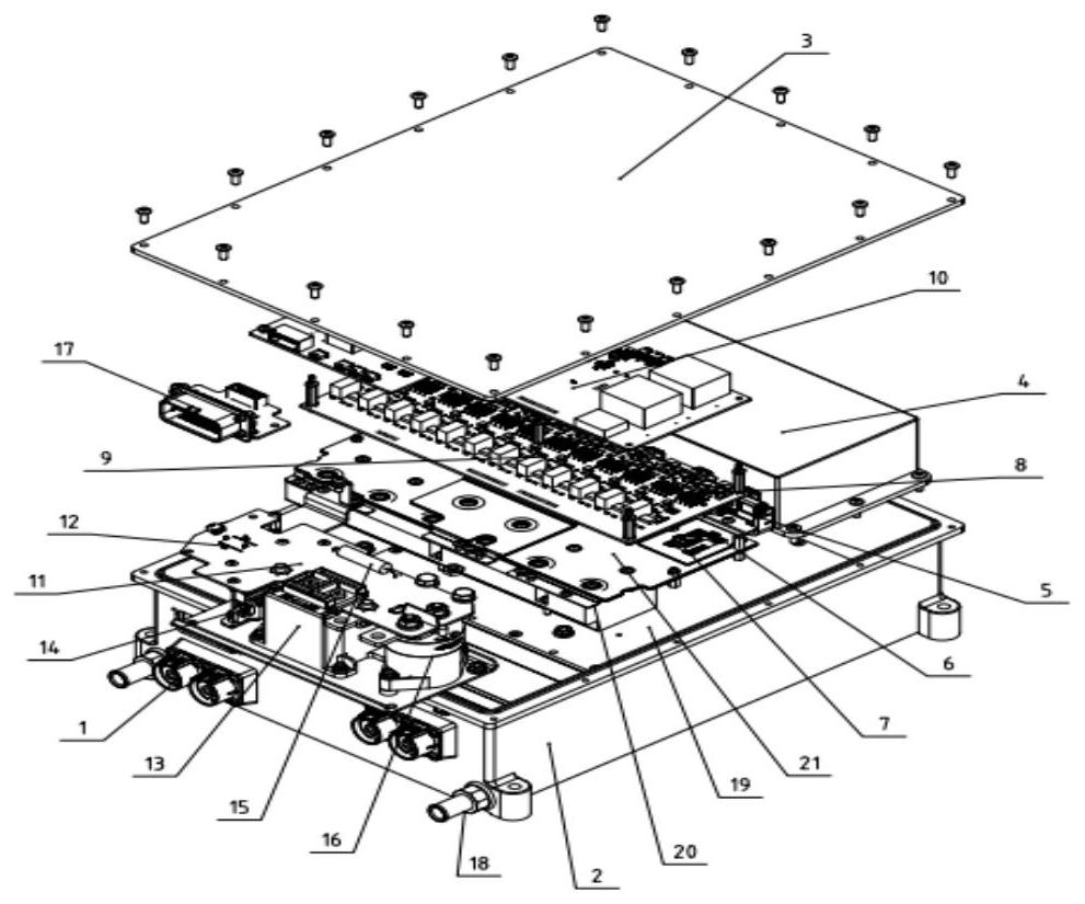
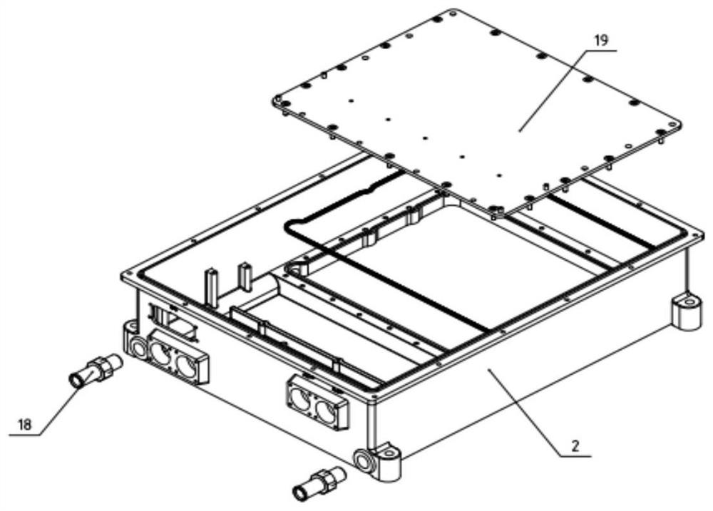
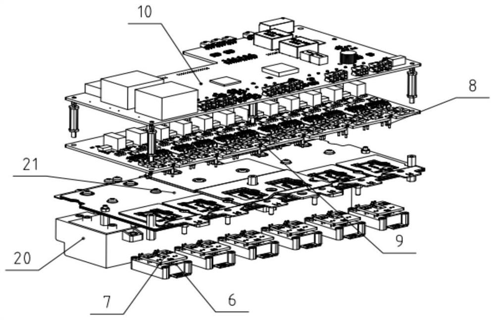
The present invention provides a vehicle-mounted SiC DCDC converter, which includes a casing, a cover, a reactor, a main control circuit board, a contactor circuit board and a film capacitor arranged inside the casing, and also includes: at least one power device, at least one The power device transfer PCB, laminated busbar, driving circuit board and spring pin; the power device transfer PCB is correspondingly arranged on the surface of the power device, and the pins of the gate G and source S of the power device are transferred to the power device PCB welding to form the first welding point, transfer the wiring on the PCB through the power device, transfer the position of the first welding point on a plane perpendicular to the pin, and expand the contact surface of the first welding point through the pad to form a welding Disk contact surface; the laminated busbar is arranged above the power device transfer PCB, and the source S and drain D of the power device are welded to the laminated busbar to form a second welding point; the drive circuit board is arranged on the laminated busbar Above the row, the drive circuit board is firmly connected to the housing; the tail end of the spring pin is welded on the drive circuit board and is arranged on the opposite side of the drive circuit board and the laminated busbar, and the spring pin has a compression-deformed head end. The drive circuit board is compressed, and is elastically connected to the contact surface of the pad through the laminated busbar to achieve elastic connection.

Description

technical field [0001] The invention relates to the field of SiC DCDC converters, in particular to a vehicle-mounted SiC DCDC converter. Background technique [0002] At present, in the application of new energy vehicle DCDC converters, the commonly used switching devices are mainly divided into two categories according to the semiconductor materials used: IGBT switching devices represented by Si semiconductor materials and SiCMOSFET power devices represented by SiC semiconductor materials. SiC power devices have the advantages of high blocking voltage, low on-state resistance, low switching loss, and high temperature resistance, which can increase the switching frequency to several times or even dozens of times of the IGBT switching frequency, effectively reducing the impact of the chopper reactor in the DCDC. Volume, weight, noise; at the same time, the reduction of on-state loss and switching loss can further reduce the design difficulty and size and weight of the heat si...

Claims


Application Information

Patent Timeline
Patent Type & Authority Patents(China)
IPC IPC(8): H02M1/00H05K1/18H05K7/20
CPCH02M1/00H05K1/181H05K7/20927
Inventor 赵丹李作伟杜太磊杨阳王长昌都泽源
Owner CRRC QINGDAO SIFANG ROLLING STOCK RES INST
Why Eureka
Try Eureka