Audio test system and test method

A technology of audio testing and testing equipment, which is applied in the direction of electrical components, etc., and can solve problems such as high testing cost, low testing efficiency, and low utilization rate of acoustic testing equipment

Inactive Publication Date: 2021-09-28
江西联创宏声吉安电子有限公司
View PDF0 Cites 0 Cited by
  • Summary
  • Abstract
  • Description
  • Claims
  • Application Information

AI Technical Summary

Problems solved by technology

However, for speaker products with a multi-speaker structure, using the current set of acoustic analysis equipment combined with a set of test fixtures to manual

Method used


Image

  • Audio test system and test method
  • Audio test system and test method
  • Audio test system and test method

Examples


Embodiment 1

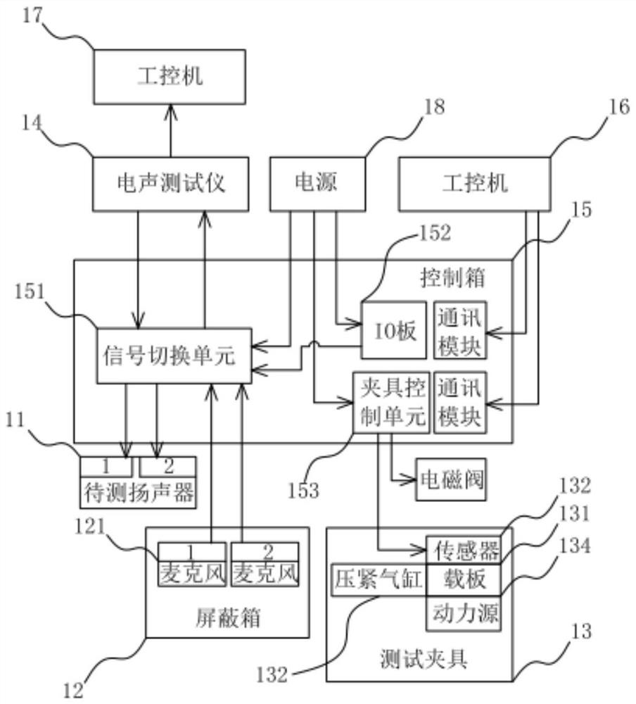
[0049] In Embodiment 1 of the present invention, as figure 1 As shown, an audio test system 10 is applied to the audio test of speakers with a multi-speaker structure; wherein, the product of a speaker with a multi-speaker structure in this embodiment is a speaker with a double-speaker structure. The audio test system 10 for the speaker to be tested 11 of the double-speaker structure includes a shielding box 12, a test fixture 13, an electroacoustic tester 14, a control box 15, an industrial computer 16 and a host computer 17, preferably, the shielding box 12. The test fixture 13, the electroacoustic tester 14, the control box 15, the industrial computer 16 and the host computer 17 are integrated on one test equipment machine. Wherein, the control box 15 includes a signal switching unit 151, an IO board 152 and a fixture control unit 153; specifically, the industrial computer 16 controls the IO board 152 and the fixture control unit 153 respectively through a communication mod...

Embodiment 2

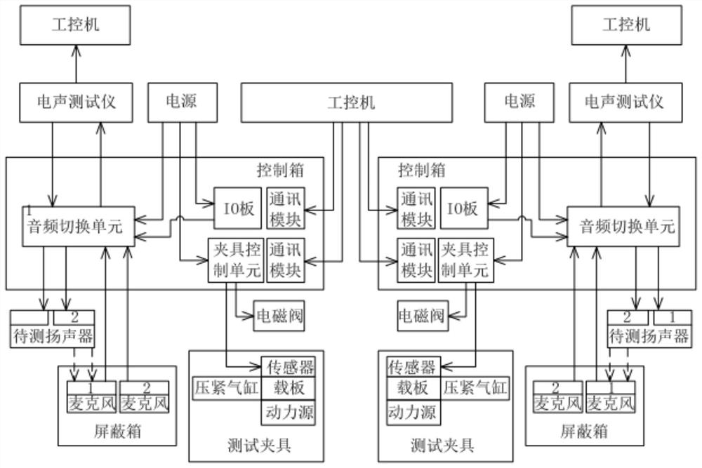
[0058] In the second embodiment of the present invention, as image 3 As shown, an audio test system is applied to the audio test of a speaker with a multi-speaker structure. In this embodiment, the audio test of two speakers with a double-speaker structure can be implemented simultaneously and independently. Its specific test system is the same as that of Embodiment 1, so it will not be repeated one by one.

Embodiment 3

[0060] In the third embodiment of the present invention, as Figure 4 As shown, an audio test method is applied to the audio test of speakers with a multi-speaker structure; the audio test method is based on the above-mentioned audio test system, and the audio test method includes the following steps S101 to S107:

[0061] Step S101: the fixture control unit receives the input signal of the level change of the Start button, sends an instruction to the industrial computer, and sends a signal to the fixture control unit after the industrial computer receives the instruction.

[0062] Step S102: The fixture control unit receives the signal, controls the compression cylinder to compress the speaker under test placed on the test fixture, and pushes the compressed speaker under test to the One side of the shielding box of the sound outlet, so that each horn sound point of the speaker to be tested is set in one-to-one correspondence with the microphone through the sound outlet, and t...


PUM


Abstract

The invention provides an audio test system and test method, and belongs to the technical field of loudspeaker audio test in electronic products. The system comprises a shielding box which is used for placing a plurality of microphones with the same number as that of a loudspeaker to be tested, a test clamp which is used for clamping the loudspeaker to be tested and pushing the loudspeaker to one side, provided with a sound outlet, of the shielding box, an electroacoustic tester, a control box which comprises a signal switching unit, an IO board and a clamp control unit, an industrial personal computer which is used for controlling the test fixture and the signal switching unit, and an upper computer which is electrically connected with the electroacoustic tester. Signal switching is carried out through a built-in audio multiplexing circuit in the signal switching unit, a time division multiplexing mode is adopted in the testing process, one-by-one full-automatic audio testing can be carried out on multiple loudspeakers in a loudspeaker product, the testing process is simplified, the testing period is shortened, the test cost is reduced, and the test efficiency and the utilization rate of acoustic test equipment are improved.

Description

technical field [0001] The invention belongs to the technical field of speaker audio testing in electronic products, and in particular relates to an audio testing system and testing method. Background technique [0002] As high-quality loudspeakers are more widely used in various electronic products, to meet consumers' new requirements for loudspeaker sound, saturation and distortion. In the speaker production process, it is necessary to check the quality of the speaker after the assembly of the electronic product. According to its sound production principle, and according to the different appearance characteristics of different electronic products, a series of audio tests need to be carried out in a special environment. Providing a rigorous testing system is an important part of reducing the negative impact of poor sound quality on product performance. [0003] With the popularization of electronic products such as smartphones and tablet computers, the market demand for sm...

Claims


Application Information

Patent Timeline
IPC IPC(8): H04R29/00
CPCH04R29/001H04R29/004
Inventor 章宏义邓智勇潘朝和乐思林黄山
Owner 江西联创宏声吉安电子有限公司
Why Eureka
Try Eureka