
Pressurizing water outlet piece

A technology of water outlet parts and water outlet chambers, applied in the direction of spraying devices, spraying devices, etc., can solve the problems of limited flushing water pressure, reduced water output of showers, insufficient water pressure, etc., to ensure stability and reliability, set up The position is flexible and diverse, stable and reliable, and the effect of alternating water discharge

Pending Publication Date: 2021-10-01
HEGII SANITARY WARE CO LTD
View PDF0 Cites 0 Cited by
  • Summary
  • Abstract
  • Description
  • Claims
  • Application Information

AI Technical Summary

Problems solved by technology

[0002] With the improvement of people's living standards, the requirements for the shower experience are getting higher and higher, but due to the lack of water pressure in the high-rise buildings and places with incomplete water supply facilities, it has become one of the problems that affect the comfort of the rain shower.
[0003] In order to solve the problem of using the low water pressure of the shower, the method of reducing the water outlet hole of the shower or reducing the diameter of the water outlet hole is mainly used at present, but the degree of increasing the flushing water pressure by these two methods is very limited, and because the reduction of the water outlet hole or the Reducing the hole diameter will lead to a significant reduction in the water output of the shower, which greatly affects the fullness of the shower and also leads to the need to spend more time in the shower

Method used


Image

  • Pressurizing water outlet piece
  • Pressurizing water outlet piece
  • Pressurizing water outlet piece

Examples


Embodiment Construction

[0047] In order to make the technical problems, technical solutions and beneficial effects to be solved by the present invention clearer and clearer, the present invention will be further described in detail below in conjunction with the accompanying drawings and embodiments. It should be understood that the specific embodiments described here are only used to explain the present invention, not to limit the present invention.

[0048]In the following discussion, details are given in order to provide a more thorough understanding of the invention. However, it will be apparent to those skilled in the art that the present invention may be practiced without one or more of these details. In certain examples, in order to avoid confusion with the present invention, some technical features known in the art are not described in detail. It should be noted that the terms "upper", "lower", "front", "rear", "left", "right" and similar expressions used herein are for the purpose of illustr...


PUM


Abstract

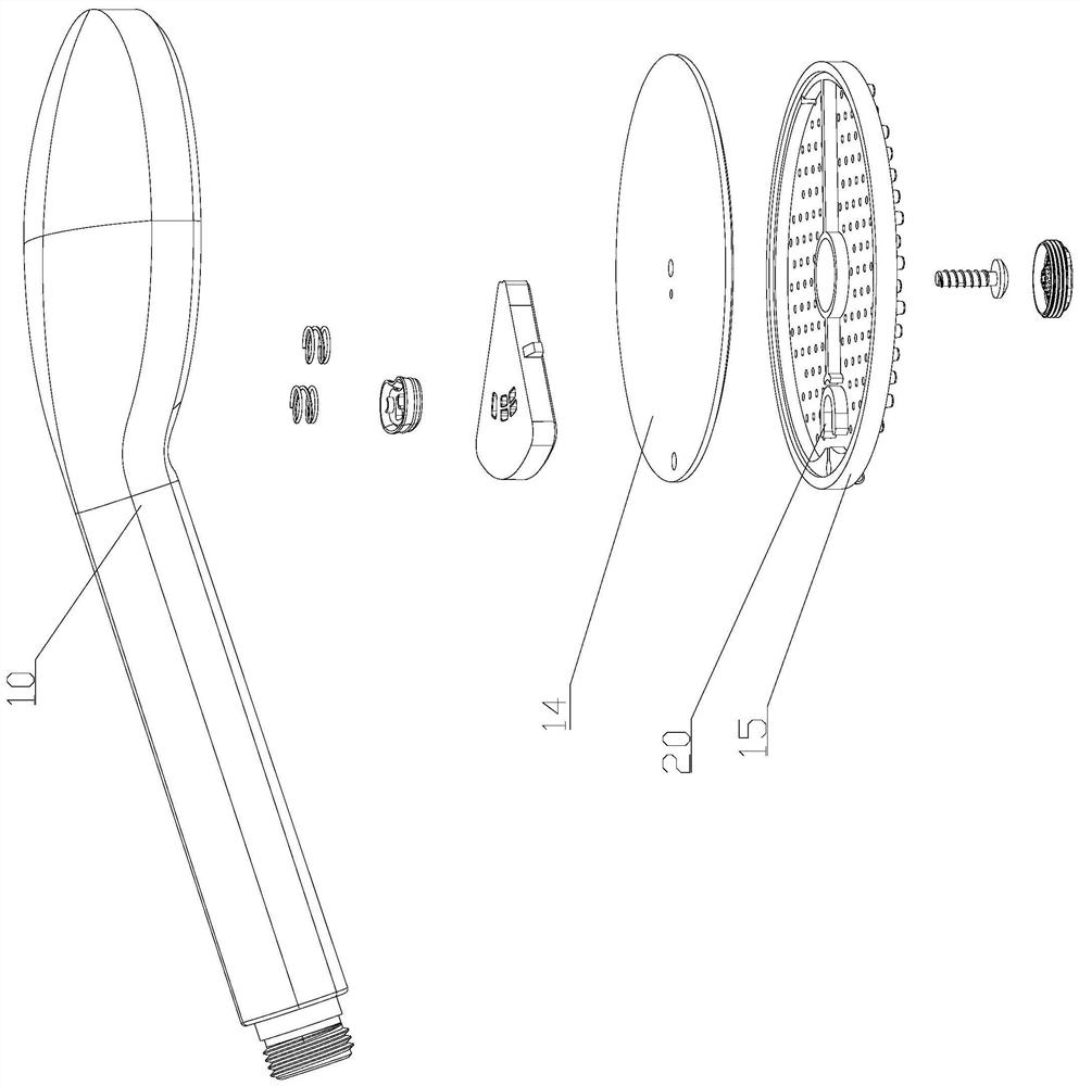
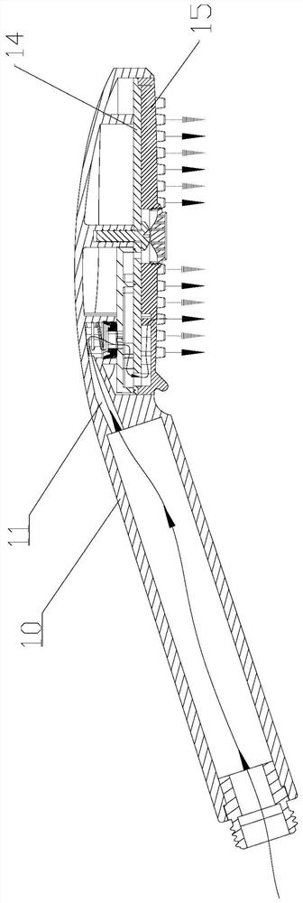
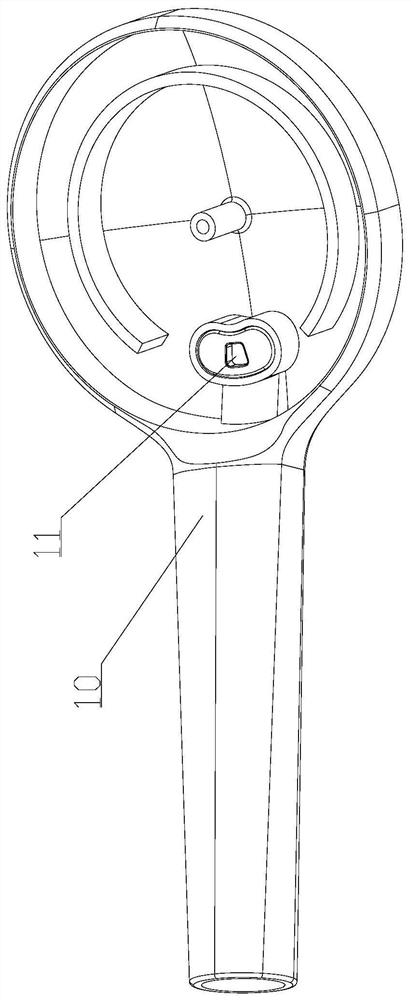
The invention discloses a pressurizing water outlet piece. The pressurizing water outlet piece comprises a body, a water inlet channel, a first water outlet channel and a second water outlet channel are arranged in the body, and the first water outlet channel and the second water outlet channel are in communication with the water inlet channel; and an alternate water outlet structure for controlling alternate water outlet of the first water outlet channel and the second water outlet channel is further arranged in the body; The alternate water outlet structure comprises a water inlet and an U-shaped control cavity, the water inlet is in communication with the water inlet channel; the opening end of the U-shaped control cavity and the water inlet are arranged at an interval, the cavity wall of the U-shaped control cavity is arranged in a bilateral symmetry mode relative to the water inlet flow direction of the water inlet, a left outlet is formed between the left side of the opening end of the U-shaped control cavity and the water inlet, the left outlet is in communication with the first water outlet channel, a right outlet is formed between the right side of the open end of the U-shaped control cavity and the water inlet, and the right outlet is in communication with the second water outlet channel. According to the scheme, the outlet water flow pressure of the water outlet piece can be improved, water flow is full, the massage effect is achieved, the structure is simple, and the function is reliable.

Description

technical field [0001] The invention relates to a pressurized water outlet component. Background technique [0002] With the improvement of people's living standards, the requirements for the shower experience are getting higher and higher, but due to the lack of water pressure in the high-rise buildings and places with incomplete water supply facilities, it has become one of the problems affecting the comfort of the rain shower. [0003] In order to solve the problem of using the low water pressure of the shower, the method of reducing the water outlet hole of the shower or reducing the diameter of the water outlet hole is mainly used at present, but the degree of increasing the flushing water pressure by these two methods is very limited, and because the reduction of the water outlet hole or the Reducing the aperture will lead to a significant reduction in the water output from the shower, which greatly affects the fullness of the shower and also results in more time spent...

Claims


Application Information

Patent Timeline
Patent Type & Authority Applications(China)
IPC IPC(8): B05B1/34B05B1/08B05B1/18
CPCB05B1/185B05B1/08B05B1/34
Inventor 谢伟藩陈雪瑜
Owner HEGII SANITARY WARE CO LTD
Learn More