

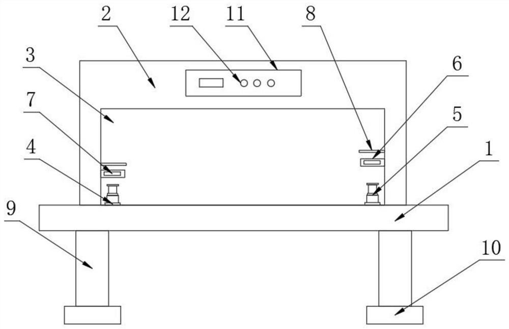
Leveling plate shearing device
A shearing device and leveling technology, which is applied in the direction of shearing devices, shearing machine accessories, feeding devices, etc., can solve the problems of long correction time, reduced work efficiency, device corrosion, etc., and achieve short correction time and low correction cost. Low, practicality-enhancing effects
- Summary
- Abstract
- Description
- Claims
- Application Information
AI Technical Summary
Problems solved by technology
Method used
Image


Examples
Embodiment approach
[0030] The specific embodiment is: the installation of the anti-corrosion device 15 is beneficial to increase the service life of the leveling device 5, reduce the cost, and is also beneficial to ensure the working efficiency of the device.
[0031] The specific reference manual is attached Figure 5 , the surface of the leveling device 5 is clamped with a fixed shaft 16 , and the size of the fixed shaft 16 matches the size of the limiting hole 14 .
[0032] The embodiment is specifically as follows: the fixing shaft 16 is provided to help fix the second set of rods 55, so as to prevent the second set of rods 55 from being ejected by the return spring 53 and affect the operation of the device.
[0033] The working principle of the present invention:
[0034] Step 1: First, the operator normally assembles the various components of the device, and then starts the device normally.
[0035]Second step: first the staff turns on the switch button 12, and then the scissors 7 start ...
PUM
 Abstract
Description
Claims
Application Information