A method for manufacturing an oil-gas separator for a screw air compressor
An oil-gas separator, a technology of a manufacturing method, applied in the directions of machines/engines, rotary piston machines, components of pumping devices for elastic fluids, etc., capable of solving problems such as unfavorable maintenance, low efficiency of oil-gas separation, and high manufacturing costs, To achieve the effects that are conducive to rapid manufacturing and processing, improve stability and reliability, and improve efficiency
Active Publication Date: 2022-06-03
衢州亿诚机械有限公司
View PDF0 Cites 0 Cited by
- Summary
- Abstract
- Description
- Claims
- Application Information
AI Technical Summary
Problems solved by technology
[0003] Due to the design defect of the oil-gas separator in the prior art, not only the efficiency of oil-gas separation is low, but also it is not conducive to maintenance, and the manufacturing cost is high
Method used
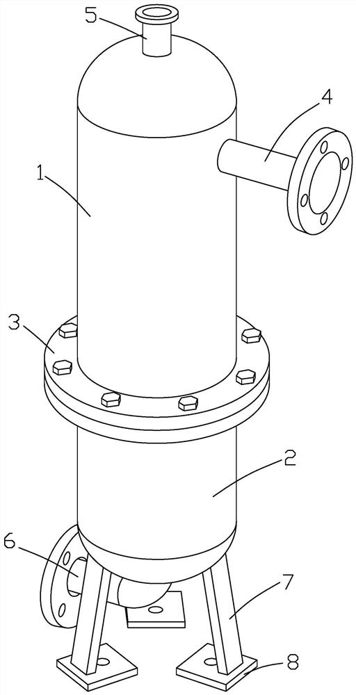
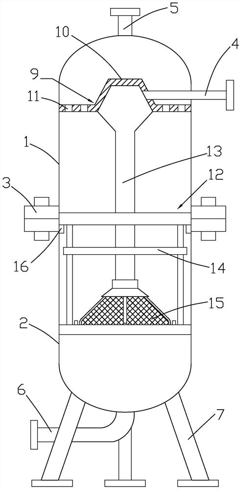
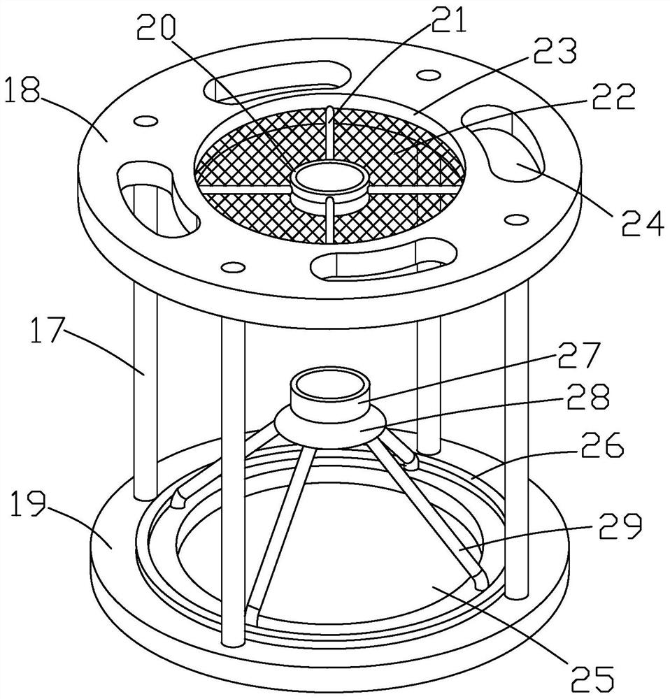
View moreImage
Smart ImageViewing Examples
Examples
Embodiment Construction
[0081] The above are only specific embodiments of the present invention, but the technical features of the present invention are not limited thereto. any
Login to View More PUM
| Property | Measurement | Unit |
|---|---|---|
| diameter | aaaaa | aaaaa |
Abstract
The invention discloses a method for manufacturing an oil-gas separator for a screw air compressor, comprising the following steps: processing an upper cylinder, processing an air transmission mechanism, processing a lower cylinder, processing a separation mechanism, assembling the oil-gas separator, and treating oil and gas. The manufacturing method of the present invention has simple steps, which not only facilitates the rapid manufacturing and processing of the oil-gas separator, but also improves the stability and reliability of the assembly of the oil-gas separator, greatly improves the efficiency of oil-gas separation, and is beneficial to ensure the stable and reliable operation of the oil-gas separator. Work.
Description
A kind of manufacturing method of oil and gas separator for screw air compressor technical field The present invention relates to a kind of manufacture method of screw type air compressor oil-gas separator. Background technique [0002] The oil and gas separator is different by the separation mechanism, and the screw air compressor adopts two different oil and gas separation methods. A sort of It is called the mechanical method, that is, the collision method or the cyclone separation method. away from oil droplets with larger diameters. The other is the affinity coalescence method, which uses elements made of special materials to make oil droplets with smaller diameters first Coalesce into directly larger oil droplets, which are then separated out. Due to the defect of design, the oil-gas separator in the prior art not only causes the efficiency of oil-gas separation to be low, but also It is not conducive to maintenance, and the manufacturing cost is high. SUMMA...
Claims
Login to View More Application Information
Patent Timeline
 Patent Type & Authority Patents(China)
IPC IPC(8): B23P15/00F04C18/16F04C29/02
CPCB23P15/00F04C29/026F04C18/16
Inventor 谭鉴郑小军
Owner 衢州亿诚机械有限公司
Features
- R&D
- Intellectual Property
- Life Sciences
- Materials
- Tech Scout
- Unparalleled Data Quality
- Higher Quality Content
- 60% Fewer Hallucinations
Learn More Browse by: Latest US Patents, China's latest patents, Technical Efficacy Thesaurus, Application Domain, Technology Topic, Popular Technical Reports.
© 2025 PatSnap. All rights reserved.Legal|Privacy policy|Modern Slavery Act Transparency Statement|Sitemap|About US| Contact US: help@patsnap.com


