Optical instrument having a stabilization element for mounting and adjusting an optical assembly in a holder, and mounting method for the stabilization element

A technology of optical components and optical instruments, applied in the field of optical instruments, can solve problems such as attenuation, lack of plastic tolerance quality, unstable vibration, etc.

Active Publication Date: 2015-07-08
HEXAGON TECH CENT GMBH
View PDF8 Cites 0 Cited by
  • Summary
  • Abstract
  • Description
  • Claims
  • Application Information

AI Technical Summary

Problems solved by technology

Furthermore, the lack of plasticity and relatively wide tolerance qualities due to incompressibility, these elements have high contact forces, making these parts not optimally suited for this installation purpose
High forces can thus occur between these components, which in turn can lead to unstable behavior and the resulting vibrations cannot be damped in the necessary manner

Method used


Image

  • Optical instrument having a stabilization element for mounting and adjusting an optical assembly in a holder, and mounting method for the stabilization element
  • Optical instrument having a stabilization element for mounting and adjusting an optical assembly in a holder, and mounting method for the stabilization element
  • Optical instrument having a stabilization element for mounting and adjusting an optical assembly in a holder, and mounting method for the stabilization element

Examples


Embodiment Construction

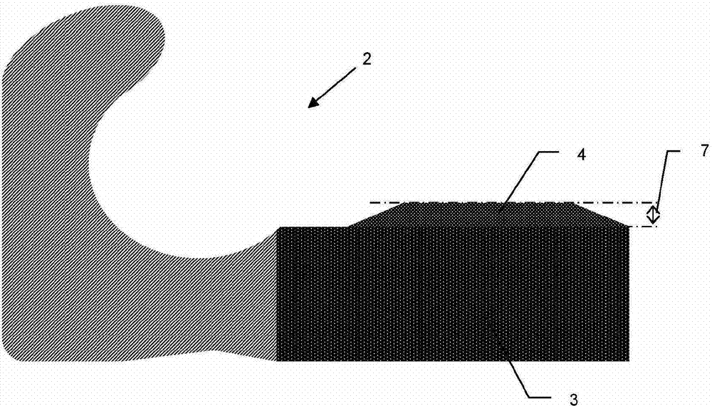
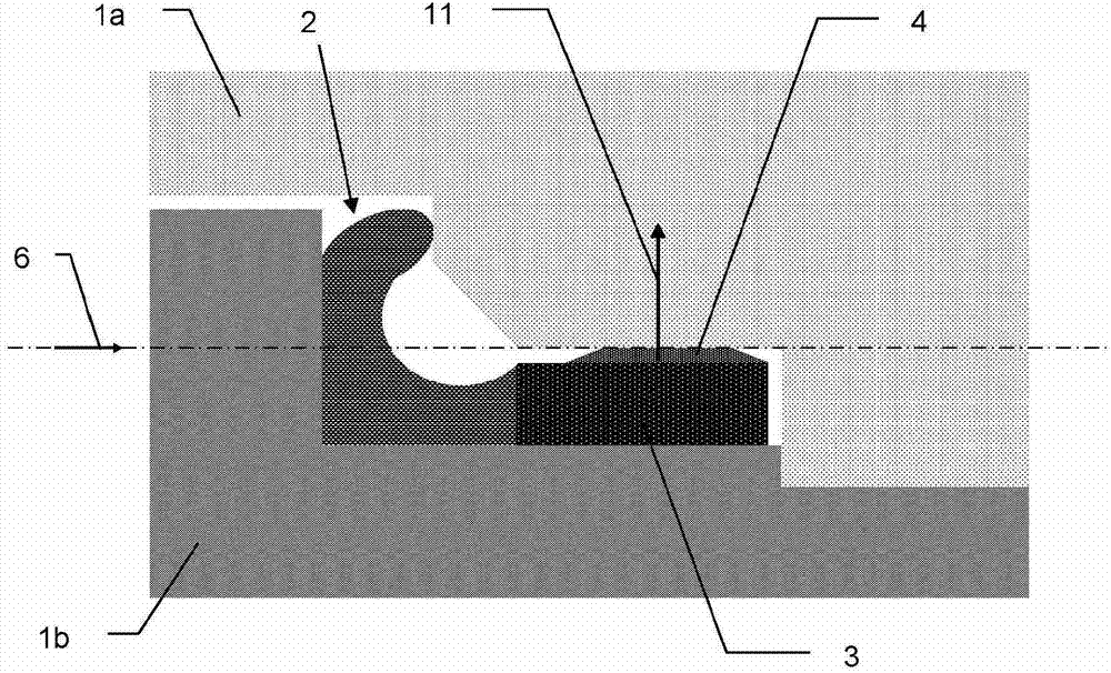
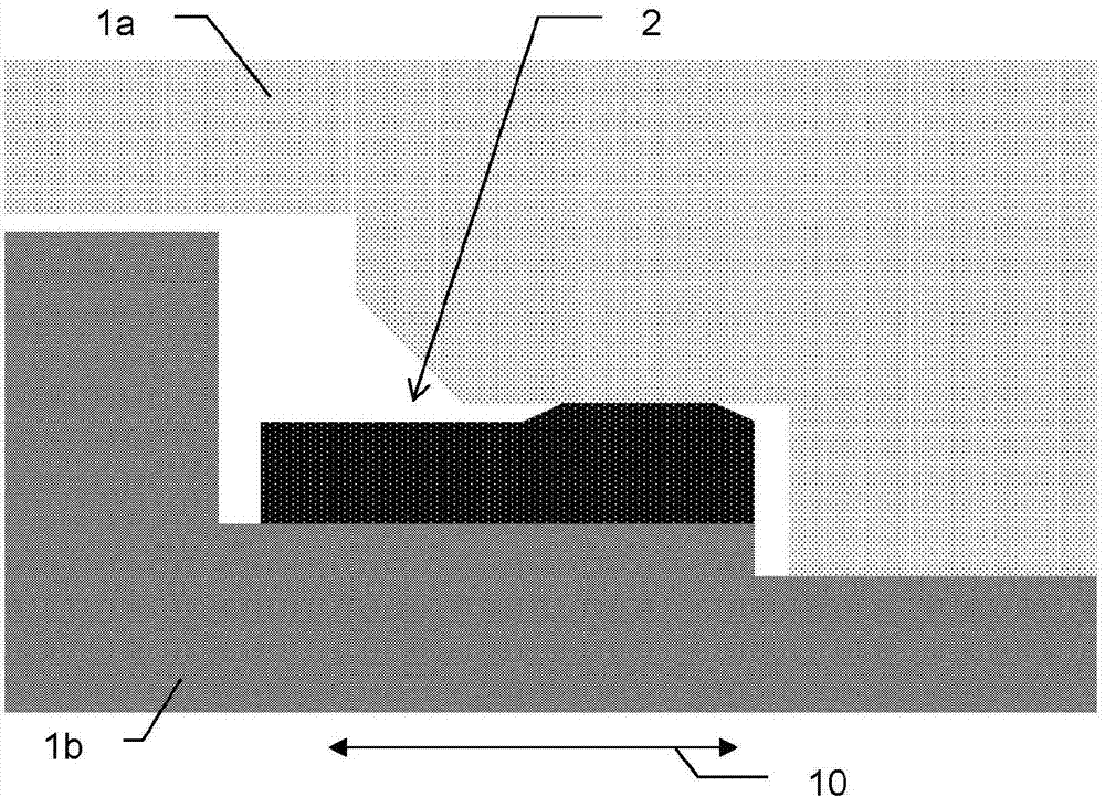
[0039] figure 1 The stabilizing element 2 according to the invention for mounting an optical component in a holder is shown in section. In this case, the stabilizing part comprises a stabilizing element 3 with a deforming element 4 . This deforming element also comprises a compression zone 7 in which the deforming element 4 deforms during mounting of the stabilizing part 2 in the optical instrument, but does not deform beyond said compressing zone.

[0040] The stabilizing element 3 with the deformation element 4 is thicker than the width of the gap that exists between the two precisely manufactured parts when they are connected to each other in the desired manner. By compressing the stabilizing element 3 , compressive stresses are generated therein which lead to plastic deformation of the deforming element 4 .

[0041] The deformation is in this case limited to a tolerance range in which the elastic compressive stress remains approximately constant in the production materia...


PUM


Abstract

The optical instrument comprises optical assembly (1b) with several optical element such as lens which defines an optical axis (8). An optical assembly holder (1a) has a shape so as to form a gap (13) with defined width between the optical assembly and holder. A stabilizing component (2) comprising stabilization elements (3a-3c) for stably connecting optical assembly and holder is provided in the gap. The stabilizing elements are deformed, so that elastic forces are acted on optical axis between assembly and holder in radial direction. The thickness of stabilizing element in an unassembled state is greater than width of gap. The optical assembly, holder and stabilizing component are connected in coarse-positioned state by inserting the optical assembly into the holder. An independent claim is included for method for mounting optical assembly to holder.

Description

technical field [0001] The invention relates to an optical instrument with an optical assembly, a holder for the optical assembly and a stabilizing element, and also to a mounting according to the preamble of claim 13 for the precise positioning of the optical assembly in the holder by means of the stabilizing element method. Background technique [0002] Optical instruments are often used to record properties of defined points in the measurement environment. Known examples of such surveying devices are geodetic devices, eg for surveying and mapping, such as theodolites or total stations. This device has angle and distance measurement capabilities, which allow direction and distance determination for selected targets. In this case, the angle and distance values ​​are determined in the device's internal reference system and may also need to be related to an external reference system for absolute position determination. [0003] In order to achieve a precise distance determ...

Claims


Application Information

Patent Timeline
Patent Type & Authority Patents(China)
IPC IPC(8): G02B7/02
CPCG02B7/023G02B7/02G02B7/026
Inventor C·艾斯利J·舍加
Owner HEXAGON TECH CENT GMBH
Why Eureka
Try Eureka