

Machine for fitting cable bushings
A cable and machine technology, applied in the field of machines for installing cable sleeves, can solve the problems of reducing the movement speed of the manipulator and increasing the acceleration drive power, so as to reduce manufacturing costs, storage costs, and fast manufacturing Effect
- Summary
- Abstract
- Description
- Claims
- Application Information
AI Technical Summary
Problems solved by technology
Method used
Image

Examples
Embodiment Construction
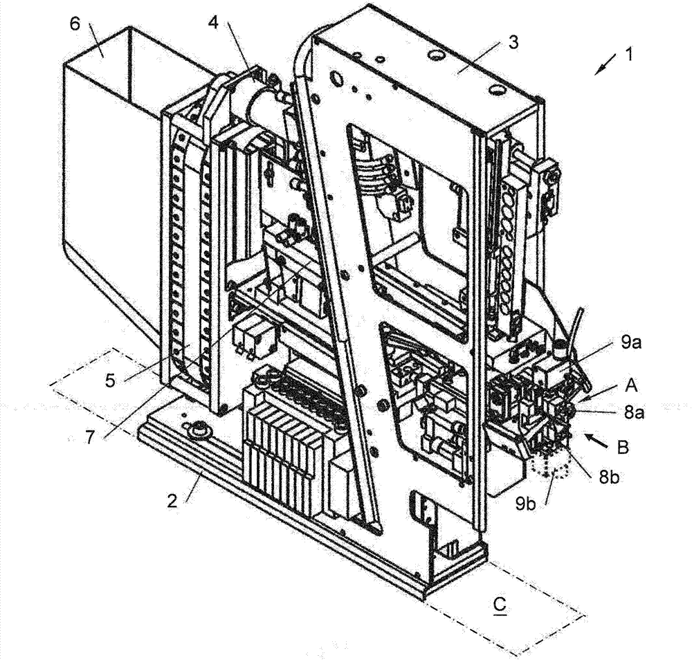
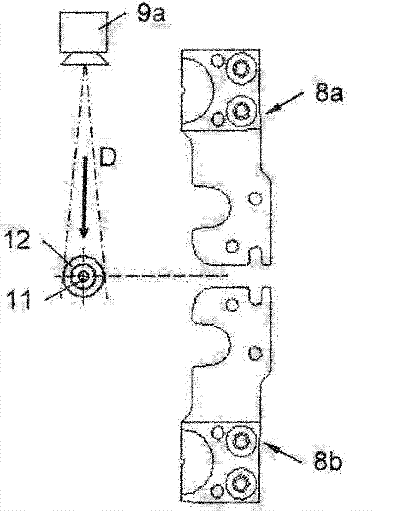
[0064] figure 1 An example view of a machine 1 for installing cable glands onto wires / cables is shown. The machine 1 comprises a frame 3 connected to a floor 2 , on which is mounted a chain conveyor 5 driven by an electric motor 4 , which is connected to a storage container 6 . Furthermore, the machine 1 comprises a vibrating rail 7, two stripping jaws 8a and 8b in the installation area A and a camera 9a, which is aimed at the installation area A (see also image 3 The observation beam in D).
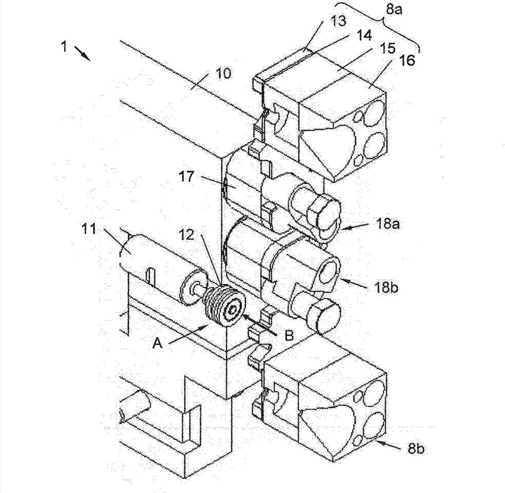
[0065] By means of a chain conveyor 5, the cable sleeves are transported one by one from the storage container 6 to the vibrating rail 7 and from the vibrating rail to the installation area A. In the installation area, the cable sleeves are installed on the wire rod / on the cable. Here, the wire / cable is delivered to the delivery device B. Details of bushing installation are in Figures 2 to 6 shown in .
[0066] exist figure 1 Also shown is the plane C required for the machine 1...
PUM
 Abstract
Description
Claims
Application Information