Edging full-automatic feeding and discharging machine

A fully automatic, feeding machine technology, applied in the direction of grinding feed movement, grinding machine parts, machine tools suitable for grinding the edge of workpieces, etc., can solve the problems of slow working rhythm and achieve the improvement of working rhythm and utilization High efficiency and good quality

Pending Publication Date: 2021-10-01
SHENZHEN JIANJIA ELECTRONICS CO LTD
View PDF8 Cites 0 Cited by
  • Summary
  • Abstract
  • Description
  • Claims
  • Application Information

AI Technical Summary

Problems solved by technology

[0007] In view of the above-mentioned related technologies, the inventor believes that there is such a feeding method. After the workpiece is processed, it needs to wait for the XYZ three-axis slide table to put the processed workpiece back to the storage place, and then remove the unprocessed workpiece from the storage place. Move to the designated position, and then the swing rod can load the unprocessed workpiece to the processing equipment, which leads to the defect that the working cycle of loading and unloading is slow

Method used


Image

  • Edging full-automatic feeding and discharging machine
  • Edging full-automatic feeding and discharging machine
  • Edging full-automatic feeding and discharging machine

Examples


Embodiment 1

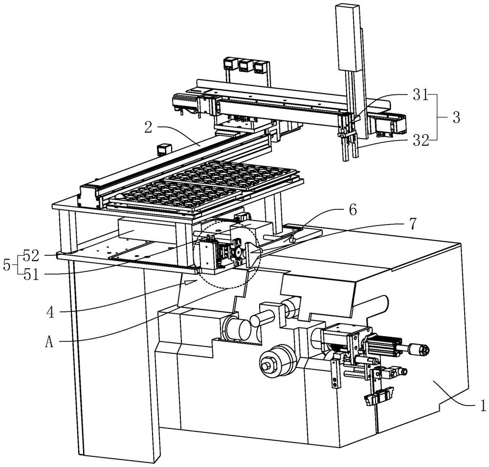
[0042] Embodiment 1, with reference to figure 1 , the core-taking automatic loading and unloading machine includes a frame 1, an XYZ three-axis slide 2 and a first pick-up part 3, the XYZ three-axis slide 2 is fixedly connected to the frame 1, and the first pick-up part 3 is fixedly connected On the XYZ three-axis slide table 2, so that itself can move on the horizontal plane and the vertical plane, specifically, the first pick-up part 3 includes a first jaw cylinder 31 and two first clamping blocks 32, the first The jaw cylinder 31 is fixedly connected to the XYZ three-axis slide table 2, and the output end of the first jaw cylinder 31 faces downward, and the two first clamping blocks 32 are respectively fixedly connected to the two sides of the first jaw cylinder 31. On the output side to be able to clamp the workpiece.

[0043] refer to figure 1 , in this embodiment, the workpiece is an optical lens in the shape of a disc, wherein the optical lens is placed in the storage...

Embodiment 2

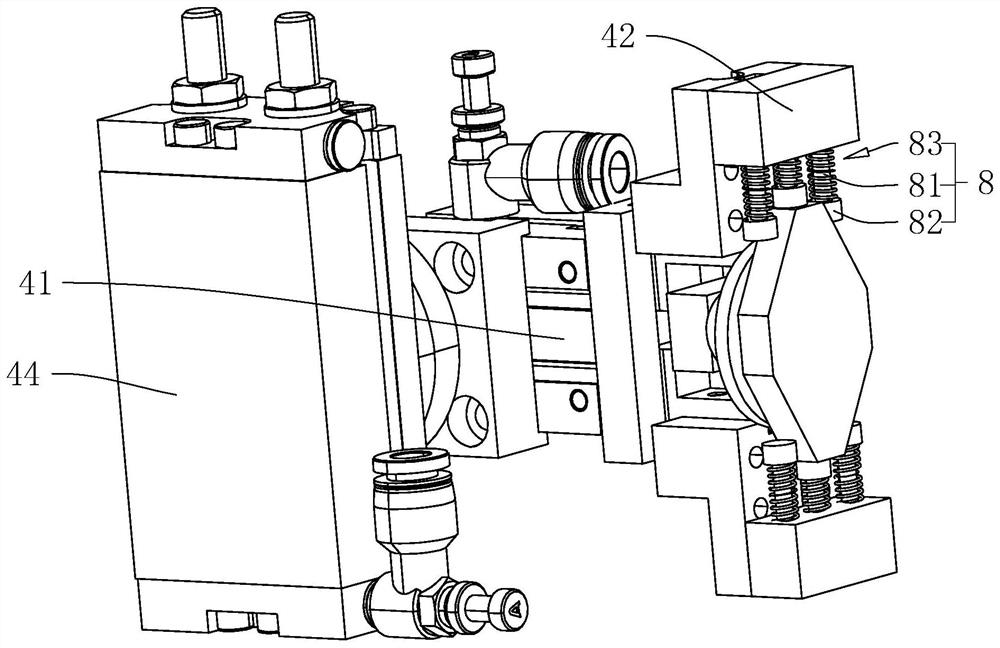
[0059] Embodiment 2, with reference to image 3 , the difference from Embodiment 1 is that an auxiliary clamping member 8 is provided on the ends of the two second clamping blocks 42 that are close to each other, and the auxiliary clamping member 8 includes a sliding rod 81, an elastic block 82 and a spring 83, wherein One end of the sliding rod 81 slides through the second clamping block 42, and the length direction of the sliding rod 81 is parallel to the line direction between the two second clamping blocks 42, and the sliding rod 81 is perpendicular to the direction of the two second clamping blocks 42. The direction of motion of the two clamping blocks 42 is evenly distributed with a plurality; the elastic block 82 is a deformable silicone material, and the elastic block 82 is fixedly connected to the end of the slide bar 81 away from the second clamping block 42; the spring 83 Then, it is sleeved on the exposed part of the sliding rod 81 outside the second clamping block...

Embodiment 3

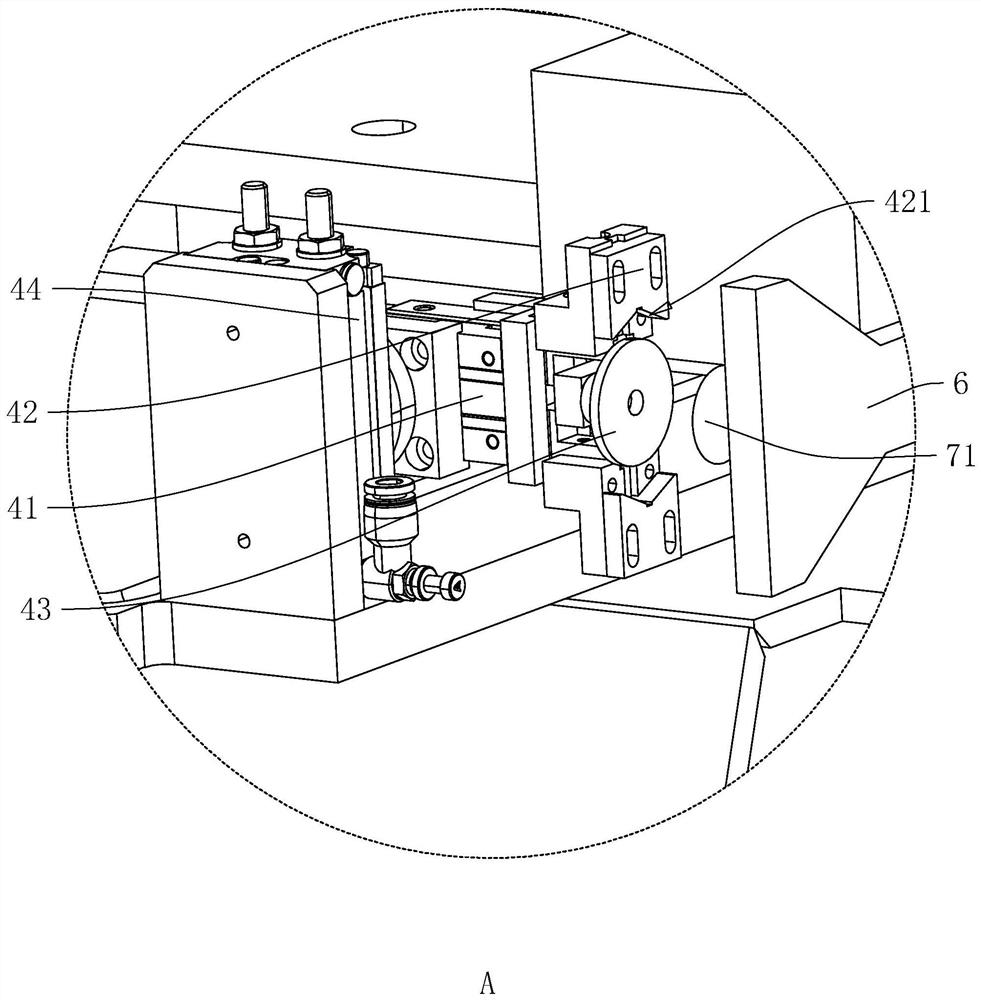
[0061] Embodiment 3, with reference to figure 2 and Figure 4 , the difference from Embodiment 1 is that the vacuum chuck 71 includes a fixed chuck 711 and two sliding chucks 712, wherein the fixed chuck 711 is fixedly connected to the swing rod 6, and the fixed chuck 711 can abut against the optical axis of the workpiece The sliding suction cup 712 is slidably connected on the fork 6, and the two sliding suction cups 712 are arranged symmetrically with respect to the fixed suction cup 711, and the two sliding suction cups 712 can slide towards the direction of approaching or moving away from each other. In addition, in this embodiment, the swinging suction cup The rod 6 is also provided with an element capable of communicating with the sliding suction cup 712 through an air path.

[0062] refer to figure 2 and Figure 4 The part of the swing rod 6 close to the vacuum suction cup 71 has an installation cavity 61 and a fixed passage 62 communicating with the installation c...


PUM


Abstract

The invention relates to an edging full-automatic feeding and discharging machine which comprises a machine frame, an XYZ three-axis sliding table arranged on the machine frame, a first material taking piece connected with the XYZ three-axis sliding table, a workpiece temporary storage piece, a driving assembly, a swing rod and a second material taking piece. The first material taking piece can slide relative to the machine frame, and the first material taking piece can take a workpiece to the XYZ three-axis sliding table; the workpiece temporary storage piece is arranged on the machine frame, and the workpiece temporary storage piece can fix the workpiece on the machine frame; the driving assembly is arranged on the machine frame, is connected with the swing rod and can enable the swing rod to rotate; and the second material taking part is arranged on the swing rod and can take the workpiece to the swing rod, the workpiece temporary storage piece is located on the movement path of the second material taking piece, and the first material taking piece can move to the movement path of the second material taking piece. The edging full-automatic feeding and discharging machine has the effect that the feeding and discharging work cycle can be improved.

Description

technical field [0001] The present application relates to the field of automatic loading and unloading equipment, in particular to a fully automatic core loading and unloading machine. Background technique [0002] Core taking machine is one of the optical machinery manufacturing equipment, which is widely used in various fields. Among them, one step in the processing flow of optical lenses is coring, which is also called edge grinding. The corresponding optical axis coincides with the geometric axis, and when the lens is to be cored, the lens needs to be put into the processing equipment through the loading and unloading equipment. [0003] In the related art, the fully automatic loading and unloading machine for core taking includes a frame, an XYZ three-axis slide table, a first retrieving part, a rotary cylinder, a swing rod and a second retrieving part, and the XYZ three-axis slide table is fixedly arranged on the frame , the first pick-up part is set on the XYZ three-...

Claims


Application Information

Patent Timeline
IPC IPC(8): B24B9/14B24B41/00
CPCB24B9/14B24B9/146B24B41/005
Inventor 程璇程亮李立
Owner SHENZHEN JIANJIA ELECTRONICS CO LTD
Why Eureka
Try Eureka