Cooling shelling mechanism based on injection molding machine and use method of cooling shelling mechanism

A technology of injection molding machine and main body, applied in the field of cooling and shelling mechanism, can solve the problems of lowering product quality, being easy to hang on the mold, time-consuming and laborious, etc., and achieving the effects of improving production quality, preventing friction and reducing workload

Inactive Publication Date: 2021-10-01
姚斌
View PDF1 Cites 1 Cited by
  • Summary
  • Abstract
  • Description
  • Claims
  • Application Information

AI Technical Summary

Problems solved by technology

[0005] In order to solve the above technical problems, the present invention provides a cooling and shelling mechanism based on an injection molding machine and its use method to solve the problem that when the existing shelling mechanism is in use, the clamping force is relatively tight for relatively small parts

Method used


Image

  • Cooling shelling mechanism based on injection molding machine and use method of cooling shelling mechanism
  • Cooling shelling mechanism based on injection molding machine and use method of cooling shelling mechanism
  • Cooling shelling mechanism based on injection molding machine and use method of cooling shelling mechanism

Examples


Example Embodiment

[0037] Example:

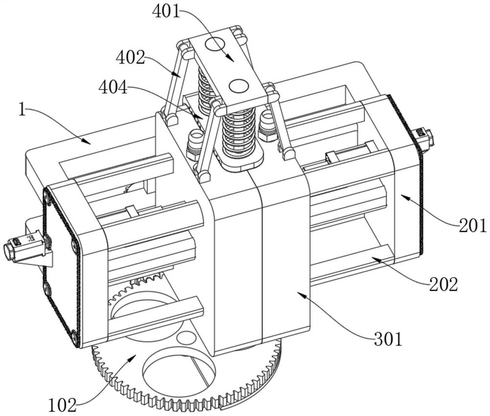
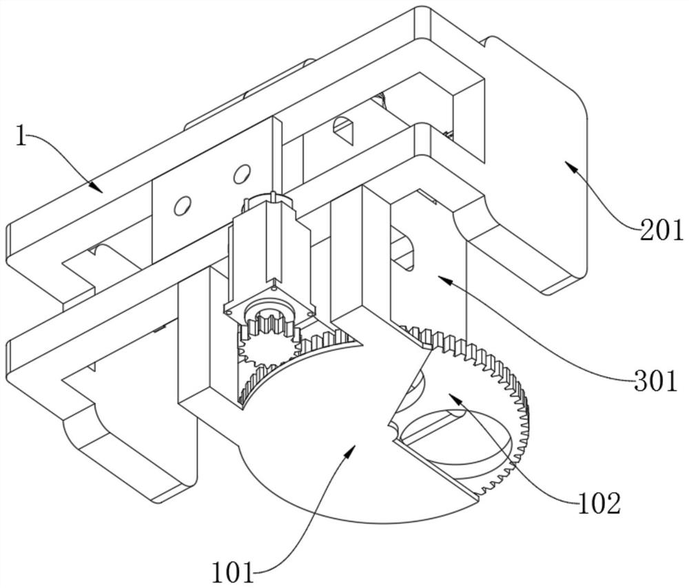
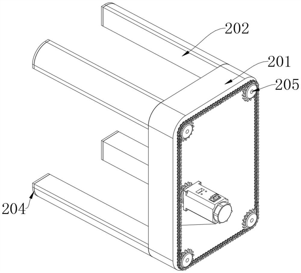
[0038] as attached figure 1 to attach Figure 7 Shown:

[0039] The invention provides a cooling and shelling mechanism based on an injection molding machine and its use method, comprising: a main body 1, a motor is installed at the bottom of the main body 1, a gear is installed at the bottom end of the motor, and a stripping part 2 is installed on the side of the main body 1 The demoulding part 2, the carrier plate 201 in the demoulding part 2 is located at the two ends of the main body 1, the side of the carrier plate 201 is equipped with a cylinder, and the side of the demoulding part 2 is equipped with a cooling part 3; The side of the splint 301 in the part 3 is provided with a plurality of openings, and the horizontal plate 202 is installed in the opening on the side of the splint 301, the side of the splint 301 is connected with the cylinder on the side of the carrier plate 201, and the slide plate in the cooling part 3 303 is located on the side of...


PUM


Abstract

The invention provides a cooling shelling mechanism based on an injection molding machine and a use method of the cooling shelling mechanism, relates to the technical field of injection molding machines, and aims to solve the problem that when an existing shelling mechanism is used, a relatively small part of a mold is forcibly pulled and is liable to be broken. The cooling shelling mechanism comprises a main body and a demolding part, a motor is mounted at the bottom of the main body, and the demolding part is mounted on the side face of the main body; and carrier plates in the demolding part are arranged at the two ends of the main body, air cylinders are mounted on the side faces of the carrier plates, and a cooling part is mounted on the side face of the demolding part. A plurality of holes are formed in the side face of a clamping plate in the cooling part, transverse plates are mounted in the holes in the side face of the clamping plate, the side face of the clamping plate is connected with the air cylinders on the side faces of the carrier plates, and a sliding plate in the cooling part is arranged on the side faces of the carrier plates. A pushing part is mounted at the top of the clamping plate, and a supporting plate in the pushing part is mounted at the edge of the top of the clamping plate through a rotating shaft. A pushing plate pushes a cross rod to move, so that an inner plate vibrates, and a plastic product is separated from the inner plate.

Description

technical field [0001] The invention belongs to the technical field of injection molding machines, and more specifically relates to a cooling and shelling mechanism based on injection molding machines and a use method thereof. Background technique [0002] In the molding process of the injection molding machine, firstly, granular or powdery plastic is added into the barrel, and the plastic is melted through the rotation of the screw and the outer wall of the barrel is heated, so that the screw is pushed forward, so that the screw is pushed forward with high pressure and fast The molten material is injected into the closed mold with a relatively low temperature at a high speed, and after a certain period of time and pressure, it is maintained and cooled to make it solidify and form, and then the mold can be opened and the product can be taken out. [0003] For example, the application number: CN201810383278.X relates to an injection mold capable of rapid cooling and demouldin...

Claims


Application Information

Patent Timeline
IPC IPC(8): B29C45/40B29C45/73
CPCB29C45/40B29C45/4005B29C45/73
Inventor 姚斌
Owner 姚斌
Why Eureka
Try Eureka