
Overturning, distributing and conveying device

A technology of conveying device and material plate, which is applied in the direction of conveyor objects, transportation and packaging, etc., can solve the problems of inconvenience, expensive manipulator, and high maintenance cost.

Active Publication Date: 2021-10-01
SHANDONG VOCATIONAL COLLEGE OF SCI & TECH
View PDF4 Cites 3 Cited by
  • Summary
  • Abstract
  • Description
  • Claims
  • Application Information

AI Technical Summary

Problems solved by technology

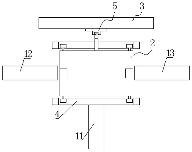
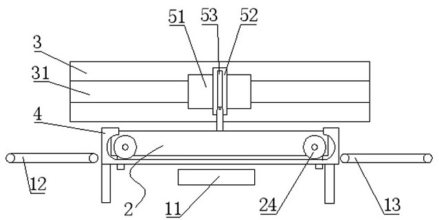
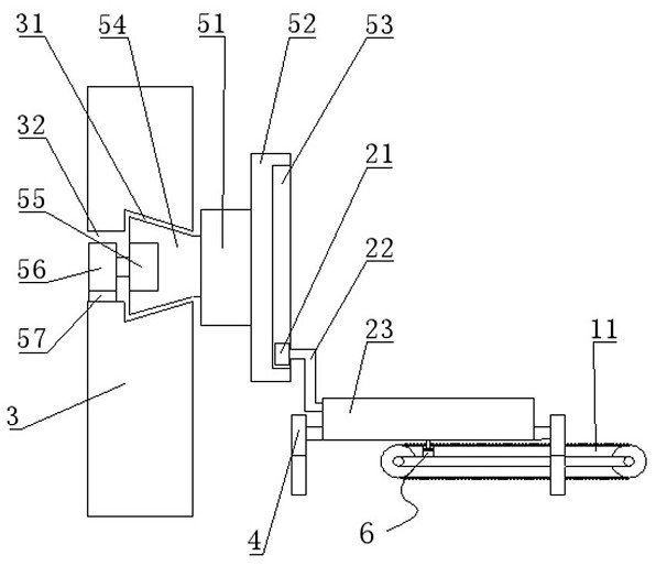
[0002] Square workpieces usually need to be turned over during production and processing, and drilling is the most common process for workpiece processing. See Figure 10 , the first conveying assembly 11 conveys a square workpiece. Looking down at the square workpiece on the first conveying assembly 11, the top surface is A surface, the left side is B surface, and the right side is C surface. At this time, the square workpiece needs to be drilled through the hole. The hole needs to go through the two opposite sides B and C of the square workpiece, so the square workpiece needs to be turned over first, so that the B or C side of the square workpiece is facing upwards, and then the drilling process is performed, so the workpiece is turned left or It can be reversed to the right, and in order to prevent workpieces from being piled up due to processing on the same conveying line, the workpieces on the conveying line are generally divided into two conveying lines for processing, that is, the workpieces on the first conveying assembly 11 are alternately turned to the left Flip right, turn left and enter the second conveying assembly 12, and turn right and enter the third conveying assembly 13, realize double-station processing, double-station processing has high efficiency, and avoids collisions caused by workpiece accumulation. In the prior art, there are The manipulator is specially used for turning and distributing, but the manipulator is expensive and the maintenance cost is high
[0003] In summary, there are obviously inconveniences and defects in the actual use of the existing technology, so it is necessary to improve

Method used


Image

  • Overturning, distributing and conveying device
  • Overturning, distributing and conveying device
  • Overturning, distributing and conveying device

Examples


Embodiment Construction

[0015] In order to make the object, technical solution and advantages of the present invention clearer, the present invention will be further described in detail below in conjunction with the accompanying drawings. It should be understood that the specific embodiments described here are only used to explain the present invention, not to limit the present invention.

[0016] It should be noted that, in the description of the present invention, terms such as "upper", "lower", "left", "right", "inner", "outer" and other indicated directions or positional relationships are based on the terms shown in the accompanying drawings. The direction or positional relationship shown is only for convenience of description, and does not indicate or imply that the device or element must have a specific orientation, be constructed and operated in a specific orientation, and thus should not be construed as limiting the present invention.

[0017] In addition, it should be noted that, in the desc...


PUM


Abstract

The invention is applicable to the technical field of square workpiece conveying, and provides an overturning, distributing and conveying device. The overturning, distributing and conveying device comprises a supporting seat arranged on the upper portion of the tail end of a first conveying assembly, wherein a distributing and conveying assembly is arranged on the supporting seat; a second conveying assembly is arranged on the left side of the distributing and conveying assembly; a third conveying assembly is arranged on the right side of the distributing and conveying assembly; the side, opposite to the first conveying assembly, of the distributing and conveying assembly is fixedly connected with an overturning driving assembly; and the overturning driving assembly is movably connected to a supporting plate. Therefore, the overturning, distributing and conveying device is simple in structure and low in cost, stable overturning of square workpieces can be achieved, the square workpieces on the same conveying line can be divided into two conveying lines, the conveying direction of the square workpieces can be changed, and interval conveying of the square workpieces can be achieved.

Description

technical field [0001] The invention relates to the technical field of conveying square workpieces, in particular to an overturning and distributing conveying device. Background technique [0002] Square workpieces usually need to be turned over during production and processing, and drilling is the most common process for workpiece processing. See Figure 10 , the first conveying assembly 11 conveys a square workpiece. Looking down at the square workpiece on the first conveying assembly 11, the top surface is A surface, the left side is B surface, and the right side is C surface. At this time, the square workpiece needs to be drilled through the hole. The hole needs to go through the two opposite sides B and C of the square workpiece, so the square workpiece needs to be turned over first, so that the B or C side of the square workpiece is facing upwards, and then the drilling process is performed, so the workpiece is turned left or It can be reversed to the right, and in ord...

Claims


Application Information

Patent Timeline
IPC IPC(8): B65G47/248B65G47/71
CPCB65G47/248B65G47/71
Inventor 辛伟坤
Owner SHANDONG VOCATIONAL COLLEGE OF SCI & TECH
Learn More