Manipulator with hydraulic quick-change connector

A manipulator and hydraulic technology, which is applied to mechanically driven excavators/dredgers, earth movers/shovels, construction, etc., can solve the problems of dust-proof and blocking of hydraulic interfaces, inability to push attachments through oil cylinders, fixation, etc.

Pending Publication Date: 2021-10-01
THE SMARTECH INST
View PDF1 Cites 0 Cited by
  • Summary
  • Abstract
  • Description
  • Claims
  • Application Information

AI Technical Summary

Problems solved by technology

[0005] The purpose of the present invention is to provide a manipulator with a hydraulic quick-change joint for the deficiencies of the prior art. By setting the quick-change joint between the third arm and the attachment, an oil cylinder is arranged on the quick-change joint, and the oil cylinder Slidingly set the push piece at both ends, set the expansion component and the hydraulic interface a at one end of the push piece, slide and set a number of extrusion pieces on the push piece, set up a number of liquid storage tanks in the push piece, and set up a number of liquid storage tanks in the liquid storage tank It stores liquid oil inside, and slides and sets the hydraulic interface b on both sides of the attachment, which solves the problem that the attachment cannot be fixed by pushing the oil cylinder when the attachment is replaced, and the quick-change joint and the attachment cannot be tightly fitted after installation. Hydraulic interface for dust cover and other issues

Method used


Image

  • Manipulator with hydraulic quick-change connector
  • Manipulator with hydraulic quick-change connector
  • Manipulator with hydraulic quick-change connector

Examples


Embodiment 1

[0034] Embodiments of the present invention are described in detail below, examples of which are shown in the drawings, wherein the same or similar reference numerals designate the same or similar elements or elements having the same or similar functions throughout. The embodiments described below by referring to the figures are exemplary and are intended to explain the present invention and should not be construed as limiting the present invention.

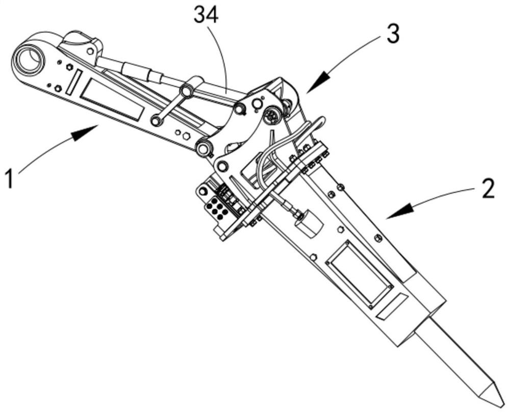
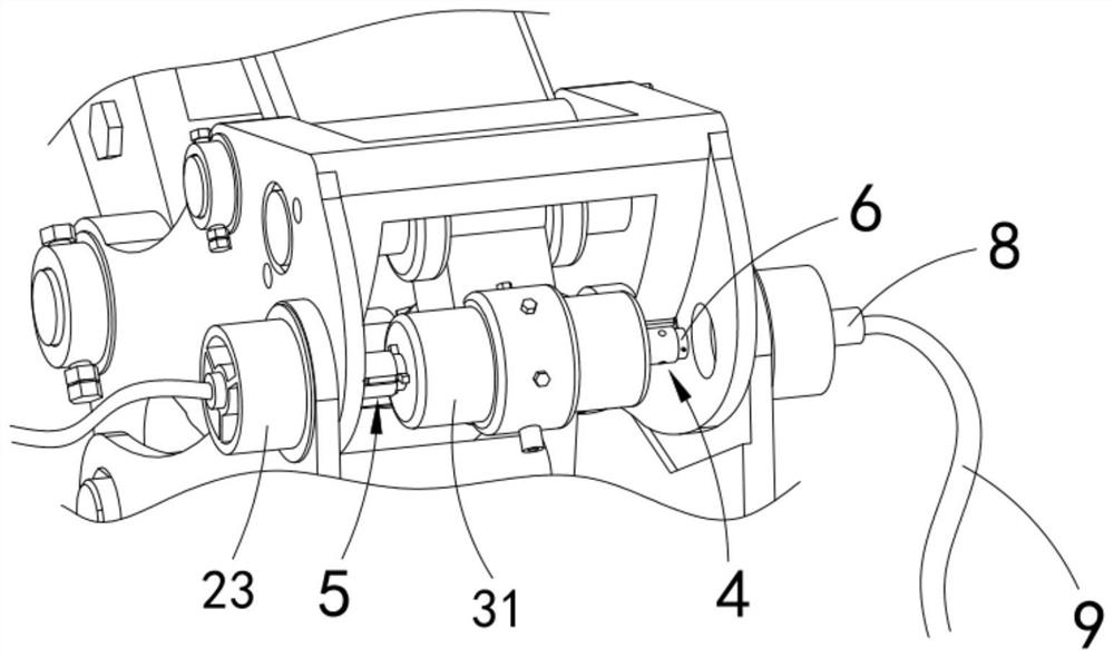
[0035] Such as Figure 1 to Figure 10 As shown, a manipulator with a hydraulic quick-change joint includes a third arm 1 and an attachment 2, a quick-change joint 3 is arranged between the third arm 1 and the attachment 2, and the quick-change joint 3 is provided with There is an oil cylinder 31, the two ends of the oil cylinder 31 are slidingly provided with a pusher 4, one end of the pusher 4 is provided with an expansion assembly 5 and a hydraulic interface a6, and a number of extruding parts are slidably arranged on the pushe...

Embodiment 2

[0047] Such as Figure 8 As shown, the parts that are the same as or corresponding to those in Embodiment 1 adopt the reference numerals corresponding to Embodiment 1. For the sake of simplicity, only the differences between Embodiment 1 and Embodiment 1 are described below; the differences between Embodiment 2 and Embodiment 1 The difference is that a cover 53 is also provided on one side of the arc panel 52 .

[0048] Here, in this embodiment, a cover 53 is provided on the side of the arc panel 52. When the quick-change joint 3 is not equipped with the attachment 2, it can effectively prevent impurities and dust in the working area from entering the hydraulic interface a6, and prevent impurities from affecting the next replacement and installation. Tool 2 makes an impact.

[0049] work process

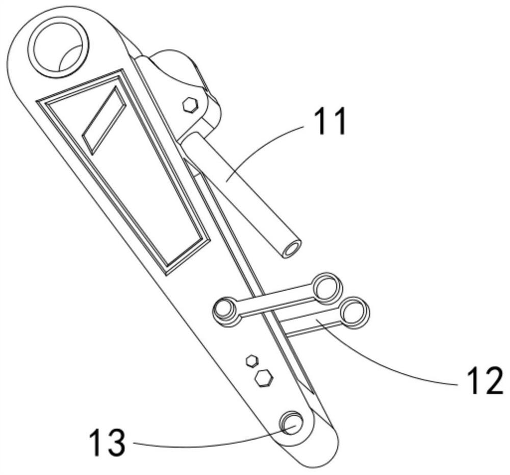
[0050] First, the driver operates the third arm 1 to drive the quick-change joint 3 to move to the top of the attachment 2 to be installed, and then locks the round rod 24 with the...


PUM


Abstract

The invention relates to a manipulator with a hydraulic quick-change connector, which comprises a third arm, an accessory, the quick-change connector, an oil cylinder, a pushing part, an expanding and supporting assembly, a hydraulic connector a, an extrusion part, a liquid storage tank and a hydraulic connector b; liquid oil is stored in the liquid storage tank; the oil cylinder pushes the pushing part to the two sides; the extrusion part extrudes the liquid oil in the liquid storage tank in the lateral moving process of the pushing part; the expanding and supporting assembly expands outwards and is fixed under the pressure of hydraulic oil; and the hydraulic connector b is in butt joint with the hydraulic connector a which is separated from shielding of the expanding and supporting assembly through magnetic adsorption. The problems that when the accessory is replaced at present, the accessory cannot be fixed through pushing of the oil cylinder, after installation, the quick-change connector and the accessory cannot be in tight joint, and dustproof shielding cannot be conducted on the hydraulic connector are solved.

Description

technical field [0001] The invention relates to the technical field of mechanical equipment, in particular to a manipulator with a hydraulic quick-change joint. Background technique [0002] Excavator quick-change joints are a kind of construction machinery accessories. It is one of the construction machinery working device accessories specially designed and developed for the specific work requirements of excavators. The mechanical quick-change joint can be used without modifying the excavator pipeline and hydraulic system, while the hydraulic quick-change joint needs to modify the excavator pipeline and hydraulic system to meet the needs of automatic replacement of working devices. [0003] A Chinese invention patent with the publication number CN106499897B discloses a quick-change joint, which includes a cylindrical locking sleeve. A cylindrical locking frame is inserted and movably connected to the locking sleeve. The locking frame A connecting pipe is inserted inside, a...

Claims


Application Information

Patent Timeline
Patent Type & Authority Applications(China)
IPC IPC(8): E02F3/36E02F5/30
CPCE02F3/3609E02F3/3663E02F3/3668E02F5/30
Inventor 王大洪肖杰何海棋
Owner THE SMARTECH INST
Why Eureka
Try Eureka