Butterfly-shaped optical cable, sheath strip for forming same, forming method and forming device

A technology for butterfly optical cables and sheaths, applied in the field of butterfly optical cables, forming methods and devices, and sheath strips for forming, can solve problems such as cracking, reduction of optical fiber unit protection capabilities, aging, etc., so as to prolong service life, Improve the manufacturing environment and ease of operation

Active Publication Date: 2021-10-01
YANGTZE OPTICAL FIBRE & CABLE CO LTD
View PDF7 Cites 0 Cited by
  • Summary
  • Abstract
  • Description
  • Claims
  • Application Information

AI Technical Summary

Problems solved by technology

[0004] Aiming at the above defects or improvement needs of the prior art, the present invention provides a butterfly optical cable, a sheath strip for forming it, a forming method and a device, the purpose of which is to form a butterfly optical cable easily through the solder layer of the sheath strip Tear the opening so that the optical cable can be peeled off. At the same time, the easy-tearing opening formed by the plastic solder can be restored under the action of the softening energy source, thus solving the problem that the existing bow-shaped optical cable has a reduced protection ability for the optical fiber unit due to the groove design, which is easy to produce Technical problems of aging and cracking

Method used


Image

  • Butterfly-shaped optical cable, sheath strip for forming same, forming method and forming device
  • Butterfly-shaped optical cable, sheath strip for forming same, forming method and forming device
  • Butterfly-shaped optical cable, sheath strip for forming same, forming method and forming device

Examples


Embodiment 1

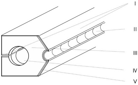
[0065] The butterfly optical cable provided by this embodiment, such as Figure 7 As shown, it includes a sheath solder layer I, a sheath flame-retardant layer III and an optical fiber unit VII; the sheath solder layer I is close to the optical fiber unit VII on one side, and has a sheath flame-retardant layer III on the other side;

[0066] The sheath solder layer I has a groove arranged longitudinally and continuously with the optical cable, and the groove is used as an easy-to-tear opening for peeling off the optical fiber unit VII, and the groove points to the optical fiber unit VII; the cross section of the groove is V-shaped;

[0067] The flame-retardant layer III of the sheath is arranged symmetrically with respect to the optical fiber unit VII in a butterfly shape, and is arranged continuously along the longitudinal direction of the optical cable with a symmetrical circular tunnel IV, and a strengthening member is arranged in the tunnel IV .

[0068] The optical fib...

Embodiment 2

[0077] The butterfly optical cable provided by this embodiment, such as Figure 8 As shown, it includes a sheath solder layer I, a sheath flame-retardant layer III and an optical fiber unit VII; the sheath solder layer I is close to the optical fiber unit VII on one side, and has a sheath flame-retardant layer III on the other side;

[0078] The sheath solder layer I has a groove arranged longitudinally and continuously with the optical cable, and the groove is used as an easy-to-tear opening for peeling off the optical fiber unit VII, and the groove points to the optical fiber unit VII; the cross section of the groove is V-shaped;

[0079] The flame-retardant layer III of the sheath is arranged symmetrically with respect to the optical fiber unit VII, and is butterfly-shaped. A symmetrical circular tunnel IV is arranged continuously along the longitudinal direction of the optical cable, and a reinforcing member VIII is arranged in the tunnel IV.

[0080] The optical fiber un...

Embodiment 3

[0089] The butterfly optical cable provided by this embodiment, such as Figure 11 As shown, it includes a sheath solder layer I, a sheath flame-retardant layer III, a bonding layer V and an optical fiber unit VII; the sheath solder layer I is close to the optical fiber unit VII on one side, and has a sheath on the other side Flame retardant layer III;

[0090] The sheath solder layer I has a groove arranged longitudinally and continuously with the optical cable, and the groove is used as an easy-to-tear opening for peeling off the optical fiber unit VII, and the groove points to the optical fiber unit VII; the cross section of the groove is V-shaped;

[0091] There is an adhesive layer V between the sheath solder layer I and the sheath flame-retardant layer III; the peeling force between the adhesive layer V and the sheath solder layer I is 14N / 15mm, and the bonding The peeling force between layer V and the flame-retardant layer III of the sheath is 13N / 15mm.

[0092] The ...


PUM

PropertyMeasurementUnit
diameteraaaaaaaaaa
diameteraaaaaaaaaa
peel strengthaaaaaaaaaa

Abstract

The invention discloses a butterfly-shaped optical cable, a sheath strip for forming the same, a forming method and a forming device. The butterfly-shaped optical cable comprises a sheath welding layer, a sheath flame-retardant layer and an optical fiber unit; wherein one side of the sheath welding layer is tightly attached to the optical fiber unit, and the other side of the sheath welding layer is provided with a sheath flame-retardant layer. The sheath strip comprises a flame-retardant layer component and a welding layer component, the flame-retardant layer component is provided with an arc-shaped matching surface matched with the optical fiber unit, and the welding layer component at least wraps the arc-shaped matching surface; and groove forming faces are arranged on the two sides of the arc-shaped matching face. According to the butterfly-shaped optical cable provided by the invention, the welding flux layer is adopted to form the longitudinally and continuously arranged grooves on the surface of the butterfly-shaped optical cable, and the grooves are used as tear-away lines. The structure not only can be conveniently and continuously prepared through the prefabricated sheath strip, but also can be recovered through the softening energy source when the optical cable is damaged, thereby facilitating the maintenance of the optical cable and prolonging the service life of the optical cable.

Description

technical field [0001] The invention belongs to the field of communication optical cables, and more specifically relates to a butterfly optical cable, a sheath strip for forming it, a forming method and a forming device. Background technique [0002] With the development of optical communication engineering in recent years, butterfly optical cable has been widely used in engineering fields such as access network and fiber-to-the-home, especially in network components such as intelligent buildings, digital communities, campus networks, and local area networks. effect. [0003] At present, in order to facilitate installation and use, the sheath of the butterfly cable has a groove structure design for easy stripping. However, the function of the sheath layer is to protect the optical fiber, and the groove structure generally needs to be aligned with the optical fiber unit, resulting in a decrease in the protection ability of the optical fiber, which is prone to aging and crack...

Claims


Application Information

Patent Timeline
Patent Type & Authority Applications(China)
IPC IPC(8): G02B6/44
CPCG02B6/443G02B6/4432G02B6/4436G02B6/4479
Inventor 沈勇杨向荣罗俊超祁林刘宏超吴帆
Owner YANGTZE OPTICAL FIBRE & CABLE CO LTD
Why Eureka
Try Eureka