Integrated high-voltage isolating switch convenient to maintain
A high-voltage isolation switch, easy maintenance technology, applied in the direction of electrical switches, air switch parts, electrical components, etc., can solve the problems of reducing the practicability of high-voltage isolation switches, the lack of convenience of the wiring head, the falling off of the wiring head, etc., so as to reduce the falling off. possibility, easy maintenance, and the effect of increasing the service life
- Summary
- Abstract
- Description
- Claims
- Application Information
AI Technical Summary
Problems solved by technology
Method used
Image
Examples
Embodiment 1
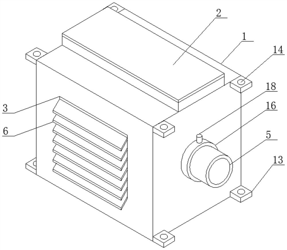
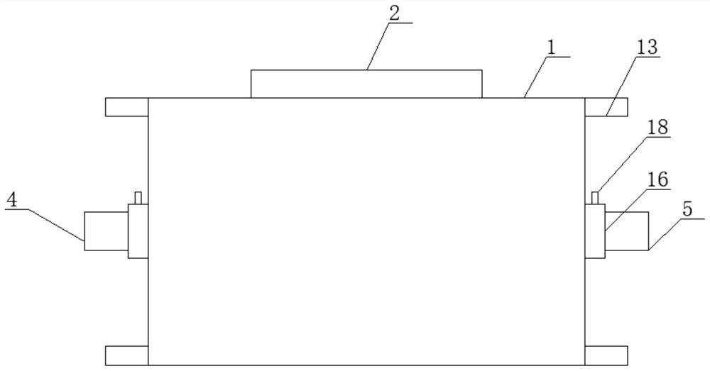
[0025] Such as Figure 1-4 As shown, the maintenance-friendly integrated high-voltage isolating switch according to the embodiment of the present invention includes a housing 1 and a cover plate 2 located at the top end of the housing 1, and the cover plate 2 is connected to the housing 1 through buckles. Connected, both sides of the housing 1 are provided with a heat dissipation port 3, the heat dissipation port 3 is provided with a matching heat dissipation mechanism, and the two sides of the housing 1 are respectively provided with a line pipe 4 and a line pipe Two 5.
Embodiment 2
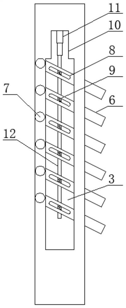
[0027] Such as Figure 1-4 As shown, the heat dissipation mechanism includes a number of uniformly distributed heat sinks 6 located in the heat dissipation port 3, the heat sinks 6 are connected to the housing 1 through a rotating shaft 7, and one side of the heat sink 6 is opened There is a chute 8 arranged obliquely, the chute 8 is provided with a sliding post 9 matching it, and the housing 1 is located at the top of the heat dissipation port 3 to open a through groove 10, and the through groove 10 The top end is provided with a telescopic cylinder 11 vertically arranged, and the bottom end of the telescopic cylinder 11 is provided with a connecting rod 12 extending into the heat dissipation port 3 and connected with the sliding column 9, and the connecting rod 12 is connected by connecting The shaft is connected with the sliding column 9, and several of the cooling fins 6 are arranged obliquely, and the two side corners of the housing 1 are respectively provided with mounti...
Embodiment 3
[0029] Such as Figure 1-4 As shown, the line tube one 4 and the line tube two 5 are respectively sleeved with matching sleeves 16, and the sleeves 16 are provided with the line tube one 4 and the line tube two respectively. Pipe two 5 are correspondingly connected to the press-down mechanism, and the press-down mechanism includes press plates 17 respectively located in the line tube one 4 and the line tube two 5, and the top of the press plate 17 is provided with a A threaded rod 18 outside the pipe one 4, a threaded groove matching the threaded rod 18 is provided on the line pipe one 4, the threaded rod 18 is connected with the pressing plate 17 through a rotating shaft, and the pressing plate 17 It is an arc structure, and the bottom end of the pressing plate 17 is provided with a rubber pad.
[0030] In order to facilitate the understanding of the above-mentioned technical solution of the present invention, the working principle or operation mode of the present invention ...
PUM
 Abstract
Description
Claims
Application Information
 - R&D
- Intellectual Property
- Life Sciences
- Materials
- Tech Scout
- Unparalleled Data Quality
- Higher Quality Content
- 60% Fewer Hallucinations
Browse by: Latest US Patents, China's latest patents, Technical Efficacy Thesaurus, Application Domain, Technology Topic, Popular Technical Reports.
© 2025 PatSnap. All rights reserved.Legal|Privacy policy|Modern Slavery Act Transparency Statement|Sitemap|About US| Contact US: help@patsnap.com


