Check patentability & draft patents in minutes with Patsnap Eureka AI!

Complementary pulse control method for thyristor

A pulse control, thyristor technology, applied in output power conversion devices, electrical components, power transmission AC networks, etc., can solve the problem that DC current cannot be established for a long time

Active Publication Date: 2021-10-01
ELECTRIC POWER RESEARCH INSTITUTE, CHINA SOUTHERN POWER GRID CO LTD
View PDF5 Cites 0 Cited by
  • Summary
  • Abstract
  • Description
  • Claims
  • Application Information

AI Technical Summary

Problems solved by technology

[0006] The invention provides a pulse supplementary control method for a thyristor, which can solve the problem that the existing random optically controlled thyristor supplementary pulse method cannot cope with the problem that the DC current cannot be established for a long time under various working conditions

Method used


Image

  • Complementary pulse control method for thyristor
  • Complementary pulse control method for thyristor
  • Complementary pulse control method for thyristor

Examples


Embodiment Construction

[0041] The following will clearly and completely describe the technical solutions in the embodiments of the present invention with reference to the accompanying drawings in the embodiments of the present invention. Obviously, the described embodiments are only some, not all, embodiments of the present invention. Based on the embodiments of the present invention, all other embodiments obtained by persons of ordinary skill in the art without creative efforts fall within the protection scope of the present invention.

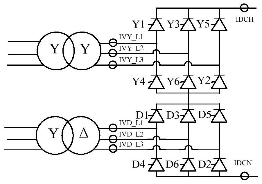
[0042]Conventional DC transmission systems generally use a 12-pulse bridge as the basic converter unit, and its structure diagram is shown in figure 1 shown. A 12-pulse bridge is composed of two 6-pulse bridges (Y bridge, D bridge) connected in series, and the commutation transformers of the two 6-pulse bridges are Y / Y and Y / △ connections respectively, and the phase difference of the two secondary side voltages is 30 °. The numbers of the single valves of the Y b...


PUM


Abstract

The invention discloses a complementary pulse control method for a thyristor. The method comprises the steps: carrying out complementary pulse enabling judgment logic on a direct-current measured value, an open-circuit test flag bit and an unlocking state flag bit, generating a complementary pulse enabling flag bit when a complementary pulse enabling condition is satisfied, transmitting the complementary pulse enabling flag bit to valve-based electronic equipment, and enabling the valve-based electronic equipment to perform complementary pulse trigger logic judgment on each single valve according to the received complementary pulse enabling flag bit, the trigger control signal of each single valve and an unlocking state flag bit so as to judge whether each single valve meets a complementary pulse trigger condition or not, and to send complementary pulse to the single valve when any single valve meets the complementary pulse trigger condition so as tomore reliably judge a starting time when the pulse needs to be supplemented to a light-controlled thyristor, so that the problem that the direct current of a direct-current power transmission system cannot be established during the unlocking period can be solved, and the problem that the direct current cannot be established for a long time under other working conditions during the non-unlocking period can be solved.

Description

technical field [0001] The invention relates to the technical field of high-voltage power transmission, in particular to a pulse compensation control method for a thyristor. Background technique [0002] High-voltage direct current transmission (HVDC: high-voltage direct current) has the advantages of strong line transmission capacity, low loss, no need for synchronous operation of the AC systems on both sides, and small losses to the power grid when a fault occurs. It is especially suitable for long-distance point-to-point transmission. Power transmission has been widely used in main transmission channels such as the West-to-East Power Transmission. [0003] For the conventional DC transmission (LCC-HVDC: Line Commutated Converter high-voltage direct current) system, when it encounters the minimum firing angle operation caused by the AC voltage drop at the sending end, the DC current fluctuation caused by the voltage drop of the AC system at the receiving end, commutation f...

Claims


Application Information

Patent Timeline
Patent Type & Authority Applications(China)
IPC IPC(8): H02M7/162H02J3/36
CPCH02M7/1626H02J3/36Y02E60/60
Inventor 陈钦磊黄立滨郭琦李书勇林雪华
Owner ELECTRIC POWER RESEARCH INSTITUTE, CHINA SOUTHERN POWER GRID CO LTD
Features
  • R&D
  • Intellectual Property
  • Life Sciences
  • Materials
  • Tech Scout
  • Unparalleled Data Quality
  • Higher Quality Content
  • 60% Fewer Hallucinations
Learn More