
Intelligent tourniquet device

A tourniquet and intelligent technology, applied in the field of intelligent tourniquet devices, can solve the problems of forgetting to release patients, waste of clinical use, inconvenient cuffs, etc., and achieve the effect of avoiding discomfort and even physical damage

Pending Publication Date: 2021-10-08
XIANGYA HOSPITAL CENT SOUTH UNIV
View PDF11 Cites 0 Cited by
  • Summary
  • Abstract
  • Description
  • Claims
  • Application Information

AI Technical Summary

Problems solved by technology

[0002] Medical cuffs are commonly used appliances in hospitals. They are mainly used in clinical nursing for venipuncture and peripheral arterial hemostasis. Most of the existing cuffs are disposable rubber products, which are wasteful, inconvenient and easy to cause the cuffs to be forgotten. solution and harm to the patient
[0003] Therefore, how to provide an intelligent tourniquet device that can adapt to the body structure of the patient and avoid the discomfort or even physical damage caused by the traditional rubber tourniquet to the patient has become a technical problem to be solved urgently by those skilled in the art.

Method used


Image

  • Intelligent tourniquet device
  • Intelligent tourniquet device
  • Intelligent tourniquet device

Examples


Embodiment 1

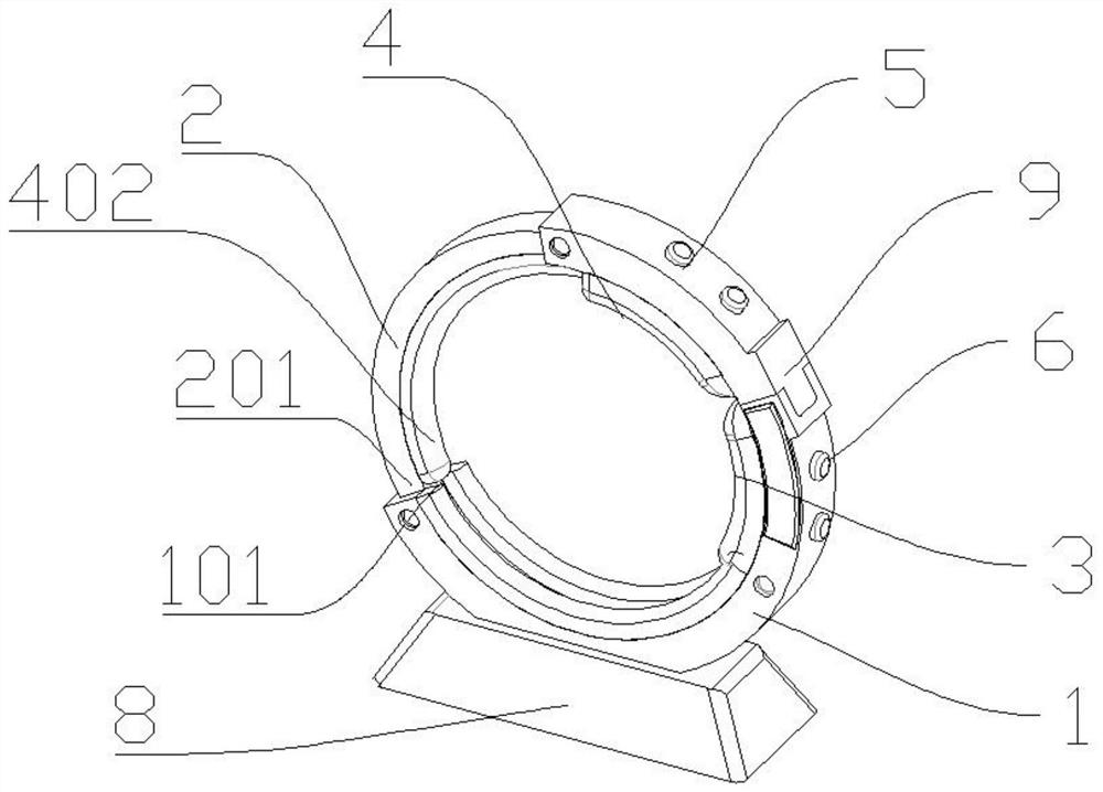
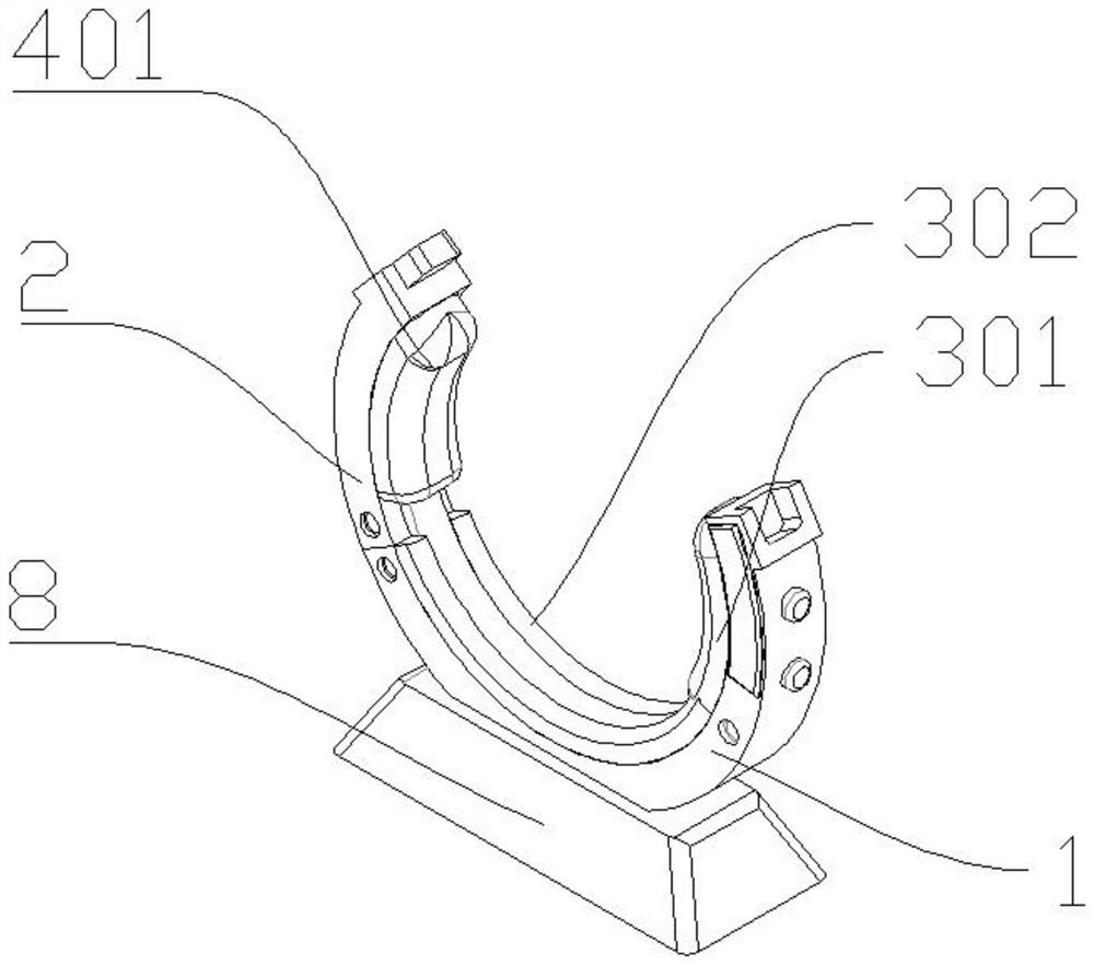
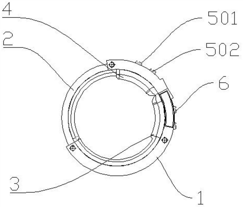
[0037] Specific as Figure 1 to Figure 4 As shown, specifically, in the embodiment of the present invention, the smart tourniquet device has a first state in which there is an insertion port for arm insertion between the first hemostatic ring body 1 and the second hemostatic ring body 2 , and the second state in which the first hemostatic ring body 1 and the second hemostatic ring body 2 form a closed ring body is specifically: the first hemostatic ring body 1 and the second hemostatic ring body 2 are slidably connected, The second hemostatic ring body 2 can move along the inner wall of the first hemostatic ring body 1 .

[0038] Specifically, in the embodiment of the present invention, the connection between the first hemostatic ring body 1 and the second hemostatic ring body 2 is as follows: a sliding track 101 is provided inside the first hemostatic ring body 1; The outside of the hemostatic ring body 2 is provided with a sliding body 201 matching the sliding track 101; th...

Embodiment 2

[0051] Specific as Figure 5 to Figure 8 As shown, see the drawings of the products involved in this embodiment for details: Specifically, the difference between this embodiment 2 and the previous embodiment 1 is that in the embodiment of the present invention, the intelligent tourniquet device has the first The first state of a hemostatic ring body 1 and the second hemostatic ring body 2 with an insertion opening for arm insertion, and the first hemostatic ring body 1 and the second hemostatic ring body 2 form a closed ring body The second state is specifically: one end of the first hemostatic ring body 1 and one end of the second hemostatic ring body 2 are hinged through the connecting shaft 7, and the end of the first hemostatic ring body 1 away from the connecting shaft 7 is connected to the The end of the second hemostatic ring body 2 away from the connecting shaft 7 has a closed locking state and an open state for sliding connection.

[0052] Specifically, in the embodi...


PUM


Abstract

Compared with the prior art, the intelligent tourniquet device disclosed by the invention comprises a first hemostatic ring; a second hemostatic ring which is connected with the first hemostatic ring; the intelligent tourniquet device has a first state in which an embedding opening for embedding an arm is formed between the first hemostatic ring and the second hemostatic ring, and a second state in which the first hemostatic ring and the second hemostatic ring form a closed ring; the first hemostatic ring and the second hemostatic ring are of arc-shaped structures; a first airbag device is arranged in the first hemostatic ring; the first airbag device has an inflated state and a deflated state. According to the technical scheme, compared with the prior art, the tourniquet device can adapt to the body structure of a patient, and discomfort and even body injury caused by a traditional rubber tourniquet device to the patient are avoided.

Description

technical field [0001] The present application relates to the technical field of clinical medical devices, and more specifically, relates to an intelligent tourniquet device. Background technique [0002] Medical cuffs are commonly used appliances in hospitals. They are mainly used in clinical nursing for venipuncture and peripheral arterial hemostasis. Most of the existing cuffs are disposable rubber products, which are wasteful, inconvenient and easy to cause the cuffs to be forgotten. solution and injury to the patient. [0003] Therefore, how to provide an intelligent tourniquet device that can adapt to the body structure of the patient and avoid the discomfort or even physical damage to the patient caused by the traditional rubber tourniquet has become a technical problem to be solved urgently by those skilled in the art. Contents of the invention [0004] In order to solve the above technical problems, the present application provides an intelligent tourniquet devic...

Claims


Application Information

Patent Timeline
Patent Type & Authority Applications(China)
IPC IPC(8): A61B17/12
CPCA61B17/12A61B2017/12004
Inventor 崔艳慧李雯潘频华
Owner XIANGYA HOSPITAL CENT SOUTH UNIV
Learn More