Raw material screening device for powder coating production

A technology of powder coating and screening device, applied in the direction of sieve, solid separation, grille, etc., can solve the problems of user's respiratory system injury and dust generation, and achieve the effect of preventing dust from flying, the device is fixed and stable, and it is convenient to move.

Inactive Publication Date: 2021-01-12
梁保永
View PDF0 Cites 0 Cited by
  • Summary
  • Abstract
  • Description
  • Claims
  • Application Information

AI Technical Summary

Problems solved by technology

[0003] In the current powder coating production and tooling process, due to the production of powder coatings that need to be sieved, and the fineness of the powder coatings, it is easy to generate dust during the vibration screening process, which will affect the operation of the internal components of the chassis, and There are certain injuries to the respiratory system of the users

Method used


Image

  • Raw material screening device for powder coating production
  • Raw material screening device for powder coating production
  • Raw material screening device for powder coating production

Examples


Embodiment 1

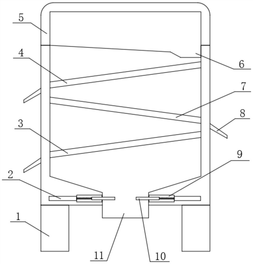
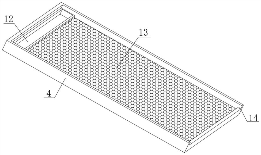
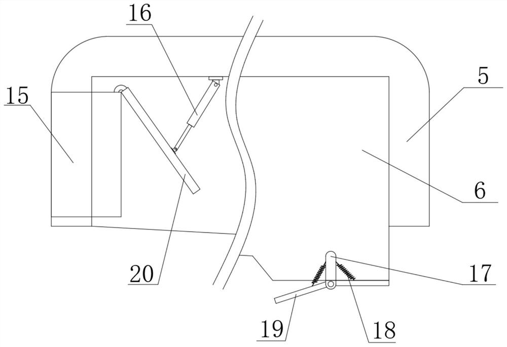
[0029] A raw material screening device for powder coating production, such as Figure 1-3 Shown, comprise main frame 5, the middle position of the inner wall of both sides of main frame 5 offers the screening chamber that vertically arranges, and the top inner wall of main frame 5 is fixed with the dust feeding box 6 that horizontal setting is arranged by bolt, and main frame 5 The top position between the inner walls of both ends of the main frame is connected with an inclined vibrating screen frame one 4 by bolts, and the middle position between the inner walls of the two ends of the main chassis 5 is fixed with an oblique vibrating screen frame two 7. The bottom between the end inner walls is connected with an inclined vibrating screen frame 3 3 by bolts, and a first hole is provided at one end of the dust feeding box 6, and the first hole is sleeved with a horizontally arranged feeding bin 15, and the feeding bin 15 One end of the top position of the dust feeding box 6 is ...

Embodiment 2

[0033] A raw material screening device for powder coating production, such as Figure 1-4 As shown, the middle of the bottom of the support column 1 is provided with a vertically arranged moving groove 23, and the top inner wall of the moving groove 23 is socketed and fixed with a vertically arranged hydraulic cylinder 22, and the middle position of the bottom of the hydraulic cylinder 22 is fixed with a vertical The moving wheel 21 that is arranged vertically, and the moving wheel 21 is socketed with the inside of the moving groove 23 .

[0034] When this embodiment is in use, in embodiment two, on the basis of embodiment one, a moving groove 23 is provided at the bottom of the support column 1, and a hydraulic cylinder 22 is sleeved on the top inner wall of the moving groove 23, and the hydraulic cylinder The bottom of 22 is equipped with mobile wheels 21. When the device is moved, the mobile wheels 21 can be directly stretched out to facilitate the movement of the device, and...


PUM


Abstract

The invention belongs to the technical field of powder coating production, in particular relates to a raw material screening device for powder coating production, and provides the following scheme forsolving the problems existing in powder raw material screening in the background art: the raw material screening device comprises a main case; vertically arranged screening cavities are formed at themiddle positions of the inner walls of the two sides of the main case; a horizontally arranged dust feeding box is fixed to the inner wall of the top of the main case through bolts; and an obliquelyarranged first vibration screen frame is connected to the top position between the inner walls of the two ends of the main case through bolts. According to the raw material screening device, a secondelectric push rod is controlled to contract, so that a feeding baffle is opened, when a powder material enters the dust feeding box, a limiting spring is stressed to extend, a discharging top plate atthe bottom position can be opened, and the smooth discharging process is performed; and through use of the second electric push rod and the limiting spring, dust in a bottom vibration area can be effectively prevented from flying up, and damage of the dust to equipment and workers is reduced.

Description

technical field [0001] The invention relates to the technical field of powder coating production, in particular to a raw material screening device for powder coating production. Background technique [0002] Powder coating is a solid powder synthetic resin coating composed of solid resin and pigments, fillers and additives. Unlike ordinary solvent-based paints and water-based paints, its dispersion medium is not solvent and water, but air. It has the characteristics of no solvent pollution, 100% film formation, and low energy consumption. There are two types of powder coatings, thermoplastic and thermosetting. [0003] In the current powder coating production and tooling process, due to the production of powder coatings that need to be sieved, and the fineness of the powder coatings, it is easy to generate dust during the vibration screening process, which will affect the operation of the internal components of the chassis, and There are certain injuries to the respirator...

Claims


Application Information

Patent Timeline
Patent Type & Authority Applications(China)
IPC IPC(8): B07B1/28
CPCB07B1/005B07B1/28
Inventor 梁保永
Owner 梁保永
Why Eureka
Try Eureka