
End socket welding device

A technology of welding equipment and heads, which is applied in the field of head welding equipment, can solve the problems of low production efficiency, large head errors, and high production costs, and achieve the effects of improving production efficiency, reducing costs, and accurate centering and horizontal positioning

Pending Publication Date: 2021-10-08
成都磐拓谷科技有限公司
View PDF7 Cites 2 Cited by
  • Summary
  • Abstract
  • Description
  • Claims
  • Application Information

AI Technical Summary

Problems solved by technology

The head needs to be welded with many accessories. Due to the large error of the head, it is impossible to accurately position the head and automatically weld the equipment.
The existing head welding methods are manual welding by professional pressure vessel welding technicians, the production efficiency is low, and the production cost is high. Manufacturers urgently need an automatic head welding equipment

Method used


Image

  • End socket welding device
  • End socket welding device
  • End socket welding device

Examples


Embodiment Construction

[0023] In order to make the object, technical solution and advantages of the present invention more clear, the present invention will be further described in detail below in conjunction with the accompanying drawings and embodiments. It should be understood that the specific embodiments described here are only used to explain the present invention, and are not intended to limit the present invention, that is, the described embodiments are only some of the embodiments of the present invention, but not all of the embodiments. The components of the embodiments of the invention generally described and illustrated in the figures herein may be arranged and designed in a variety of different configurations.

[0024] Accordingly, the following detailed description of the embodiments of the invention provided in the accompanying drawings is not intended to limit the scope of the claimed invention, but merely represents selected embodiments of the invention. Based on the embodiments of ...


PUM


Abstract

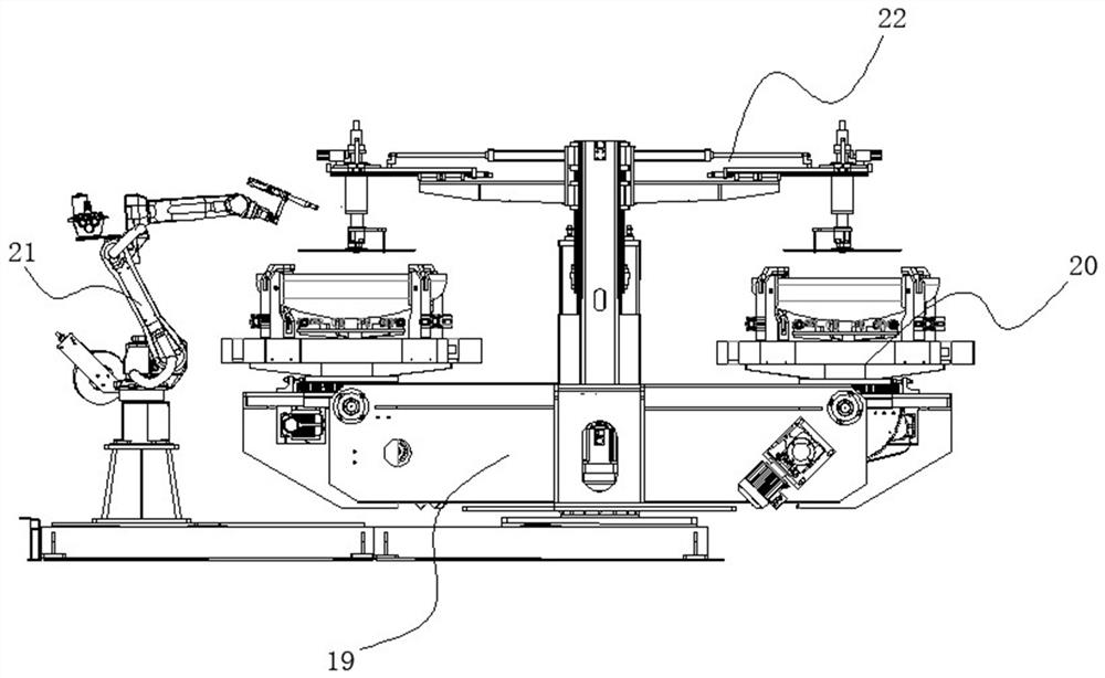
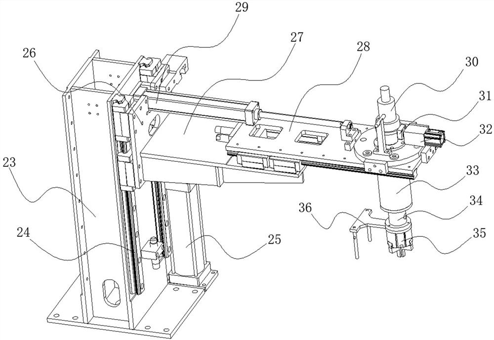
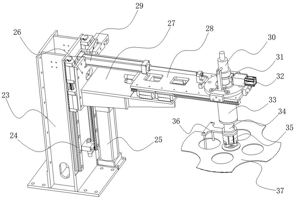
The invention relates to the technical field of end socket welding, and particularly discloses an end socket welding device. The end socket welding device comprises a rotary table, at least two end socket positioning clamps are symmetrically arranged on the rotary table around the rotary center, two welding robots are arranged on one side of the rotary table, disc positioning clamps corresponding to the end socket positioning clamps in number are arranged on the rotary table, each end socket positioning clamp corresponds to one disc positioning clamp, a supporting frame is arranged at the top of the rotary table, the disc positioning clamps are fixedly installed on the supporting frame, the disc positioning clamps are used for positioning discs on end sockets, and a jacking air cylinder is arranged at the bottom of the supporting column and used for jacking the supporting column. The end socket welding device has the advantages that the rotary table is provided with multiple stations, each station is provided with one end socket positioning clamp and one disc positioning clamp, welding can be conducted during feeding and discharging through the multiple stations, therefore, the welding efficiency is improved, manual welding is replaced, and the manufacturing cost is reduced.

Description

technical field [0001] The invention relates to the technical field of head welding, in particular to head welding equipment. Background technique [0002] The head of LNG cylinder is a product drawn from a mold with many diameters and specifications. The diameter and height of the head have large errors. The maximum diameter error is 5 mm, and the height error is 4 mm. The head needs to be welded with many accessories. Due to the large error of the head, it is impossible to accurately position the head, and the automatic welding of the equipment cannot be performed. The existing head welding methods are manual welding by professional pressure vessel welding technicians, the production efficiency is low, and the production cost is high. Manufacturers urgently need an automatic head welding equipment. Contents of the invention [0003] The object of the present invention is to overcome the disadvantages of the prior art and provide a head welding equipment. [0004] The p...

Claims


Application Information

Patent Timeline
IPC IPC(8): B23K37/047B23K37/04B25J9/04B25J9/02B25J15/08B25J11/00
CPCB23K37/047B23K37/0461B25J9/04B25J9/02B25J15/08B25J11/005
Inventor 毛斌刘波
Owner 成都磐拓谷科技有限公司
Learn More