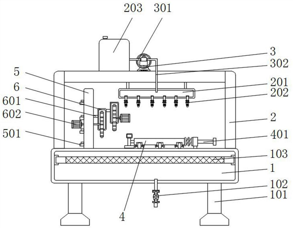
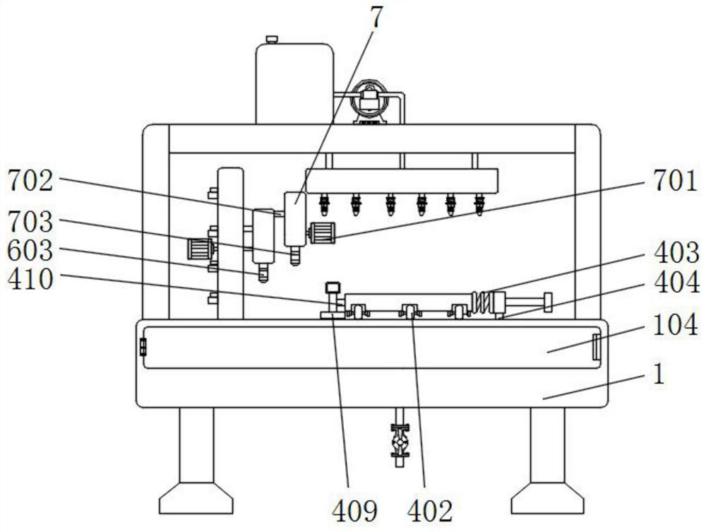
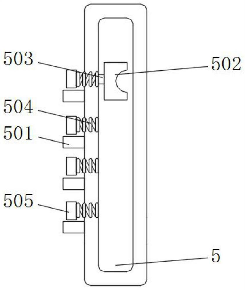
Cutting equipment for building decoration engineering

A technology for architectural decoration and cutting equipment, which is applied in metal processing and other directions, and can solve the problems of inconvenient height adjustment of protective boxes, lack of multiple blades, and displacement of building materials.

Inactive Publication Date: 2021-10-08
任欣
View PDF0 Cites 0 Cited by
  • Summary
  • Abstract
  • Description
  • Claims
  • Application Information

AI Technical Summary

Problems solved by technology

[0004] 1. When the existing cutting equipment is in use, it is inconvenient to adjust the height of the protective box, which makes the device relatively limited in cutting building materials of different thicknesses;
[0005] 2. When the existing cutting equipment is in use, it does not have the function of using multiple blades, which makes it inconvenient for the device to cut building materials of different materials;
[0006] 3. When the existing cutting equipment is in use, it does not have the function of positioning the building materials, which leads to the phenomenon that the position of the building materials is prone to shift when cutting

Method used


Image

  • Cutting equipment for building decoration engineering
  • Cutting equipment for building decoration engineering
  • Cutting equipment for building decoration engineering

Examples


Embodiment Construction

[0028] The following will clearly and completely describe the technical solutions in the embodiments of the present invention with reference to the accompanying drawings in the embodiments of the present invention. Obviously, the described embodiments are only some, not all, embodiments of the present invention. Based on the embodiments of the present invention, all other embodiments obtained by persons of ordinary skill in the art without making creative efforts belong to the protection scope of the present invention.

[0029] In the description of the present invention, it should be noted that the terms "upper", "lower", "inner", "outer", "front end", "rear end", "both ends", "one end", "another end" The orientation or positional relationship indicated by etc. is based on the orientation or positional relationship shown in the drawings, and is only for the convenience of describing the present invention and simplifying the description, rather than indicating or implying that ...


PUM


Abstract

The invention discloses cutting equipment for building decoration engineering, which comprises a base, a supporting frame, a water pump and a limiting plate; a first sliding block is installed at the top of the base; a first spring is welded to the outer wall of one side of the first sliding block; the limiting plate is welded to the outer wall of one side of the first spring; and a third sliding block is installed on the outer wall of one side of the limiting plate. According to the invention, a first protection box and a second protection box are installed; a pull plate is pulled to drive a movable rod to move; the movable rod can be separated from an embedding block through movement of the movable rod; a stretching rod can be driven to stretch out and draw back through movement of the pull plate; a fourth sliding block can extend into a groove through connection of the fourth sliding block and the first protection box; the fourth sliding block can make contact with the back face of the movable rod; the movable rod can penetrate into the fourth sliding block through an embedding groove; the movable rod can make contact with the embedding block through penetration of the movable rod; and therefore, the movable rod can be embedded into the embedding block to fix the second protection box.

Description

technical field [0001] The invention relates to the field of cutting equipment, in particular to a cutting equipment for building decoration engineering. Background technique [0002] Cutting equipment is a tool that drives the blade through a transmission mechanism for cutting operations. It has the advantages of safety, reliability, reasonable structure, and high work efficiency. It is usually suitable for cutting operations on materials such as stone and wood, and is convenient for cutting to the required size. Also more convenient. [0003] The defective that existing cutting equipment exists is: [0004] 1. When the existing cutting equipment is in use, it is inconvenient to adjust the height of the protective box, which makes the device relatively limited in cutting building materials of different thicknesses; [0005] 2. When the existing cutting equipment is in use, it does not have the function of using multiple blades, which makes it inconvenient for the device t...

Claims


Application Information

Patent Timeline
Patent Type & Authority Applications(China)
IPC IPC(8): B26D1/14B26D5/08B26D7/02B26D7/22B26D7/26B26D11/00
CPCB26D1/14B26D5/086B26D7/02B26D7/22B26D7/2635B26D11/00
Inventor 任欣
Owner 任欣
Why Eureka
Try Eureka