Die changing trolley with lifting and quick positioning functions

A technology of mold trolley and lifting table, which is applied in the field of mold changing trolley with lifting and fast positioning, which can solve the problems of difficulty in lifting and adjusting the mold table, difficulty in meeting the needs of use, and single function, so as to improve the efficiency of mold changing , Simple and reasonable structure, high mold change efficiency

Inactive Publication Date: 2021-10-08
JIANGSU ZHISHI TECH CO LTD
View PDF1 Cites 3 Cited by
  • Summary
  • Abstract
  • Description
  • Claims
  • Application Information

AI Technical Summary

Problems solved by technology

[0003] The mold change trolley is a manual or electric driven movable mold transmission system, which can realize the automatic exchange of molds in the stamping process, but in the prior art, the mold change trolley generally has a relatively complicated structure and a single function , at the same time, it is difficult to adjust the mold platform up and down, and it is difficult to meet the existing use requirements. Therefore, we have improved this and proposed a mold changing trolley with lifting and fast positioning.

Method used


Image

  • Die changing trolley with lifting and quick positioning functions
  • Die changing trolley with lifting and quick positioning functions
  • Die changing trolley with lifting and quick positioning functions

Examples


Embodiment Construction

[0023] The preferred embodiments of the present invention will be described below in conjunction with the accompanying drawings. It should be understood that the preferred embodiments described here are only used to illustrate and explain the present invention, and are not intended to limit the present invention.

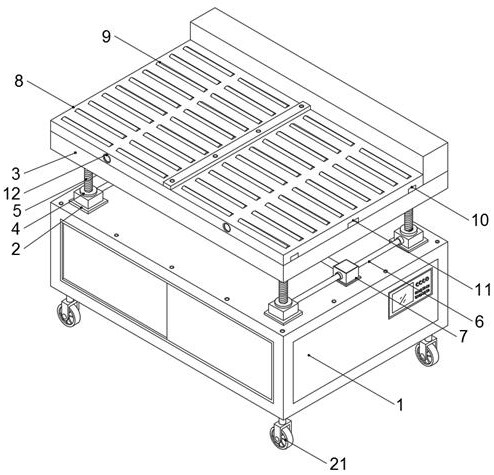
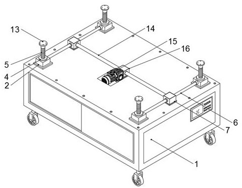
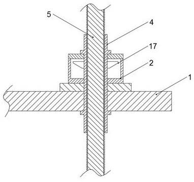
[0024] Example: such as Figure 1-4 As shown, a mold changing trolley with lifting and quick positioning of the present invention includes a main body 1, and fixed seats 2 are installed at the top four corners of the main body 1, and rotating sleeves are installed at the top of the fixed seats 2. 4. A pair of connecting seats-7 are fixedly installed on the top side of the main vehicle body 1, and the connecting seats-7 are respectively installed between the fixed seats 2, and the front and rear sides of the connecting seat-7 are connected to the transmission shaft-6 , the other end of the transmission shaft 6 is respectively connected to one side of the fixed seat 2...


PUM


Abstract

The invention discloses a die changing trolley with lifting and quick positioning functions. The die changing trolley comprises a main trolley body, fixing bases are installed at the four corners of the top end of the main trolley body correspondingly, rotating sleeves are installed at the top ends of the fixing bases correspondingly, a pair of first connecting bases is fixedly installed on the top side of the main trolley body, the first connecting bases are installed among the fixing bases correspondingly, the front sides and the rear sides of the first connecting bases are connected to first transmission shafts, the other ends of the first transmission shafts are connected to one sides of the fixing bases correspondingly, the first transmission shafts are in transmission connection with the rotating sleeves, a second connecting base is installed on the top side of the main trolley body and located between the two first connecting bases, the left side and the right side of the second connecting base are connected to second transmission shafts correspondingly, the other ends of the second transmission shafts are connected to the first connecting bases, and the second transmission shafts are in transmission connection with the first transmission shafts. The die changing trolley with the lifting and quick positioning functions is simple and reasonable in structure, novel in design, easy to operate, higher in applicability and higher in die changing efficiency.

Description

technical field [0001] The invention relates to a mold changing trolley, in particular to a mold changing trolley with lifting and fast positioning. Background technique [0002] In the current plastics industry, when a large injection molding machine needs to replace the mold, it can only be replaced by a crane and manpower. When the crane replaces the mould, it is prone to illegal operations such as crooked pulling and slanting, and the wire rope is also prone to damage the machine tool equipment during the pulling process. On the other hand, because the pulling distance is difficult to control, the operator operates completely by his own feeling, which is very easy to cause the accident that the mold slips off the ground and hurts people due to improper force. In addition, moving large molds manually is time-consuming and labor-intensive. Therefore, the mold changing trolley can be applied. [0003] The mold change trolley is a manual or electric driven movable mold tr...

Claims


Application Information

Patent Timeline
Patent Type & Authority Applications(China)
IPC IPC(8): B29C45/17
CPCB29C45/1756B29C45/1742
Inventor 范磊
Owner JIANGSU ZHISHI TECH CO LTD
Why Eureka
Try Eureka