A fast positioning latch locking device

A technology for positioning bolts and locking devices, applied in threaded fasteners, connecting components, screws, etc., can solve the problems of positioning failure, bending of bolts, large inertia, etc., to achieve perfect functions, avoid bending damage, and simple structure. Effect

Active Publication Date: 2022-05-10
CHENGDU AIRCRAFT INDUSTRY GROUP
View PDF0 Cites 0 Cited by
  • Summary
  • Abstract
  • Description
  • Claims
  • Application Information

AI Technical Summary

Problems solved by technology

However, because the tooling equipment and the fixed guide rail platform cannot be closely bonded, there will be a certain gap. In large-scale equipment with large mass and large inertia, if only relying on the pin to limit the position, there will be higher requirements for the size of the pin. Therefore, the traditional positioning The pin will be subjected to shear force brought by external force and bending moment due to excessive clearance, and eventually the pin will bend and cause positioning failure

Method used


Image

  • A fast positioning latch locking device
  • A fast positioning latch locking device
  • A fast positioning latch locking device

Examples


Embodiment 1

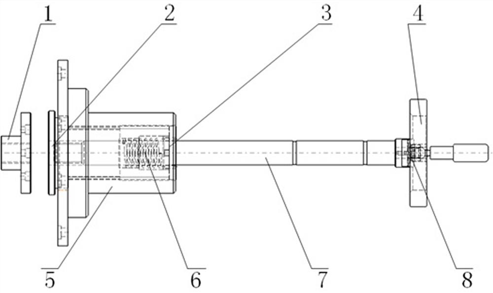
[0027] The main structure of this embodiment, such as figure 1 As shown, it includes a flange seat 5 with an internal thread, a pressing nut 2 with an external thread, a positioning pin 7 embedded in the pressing nut 2, and a fixing pin seat 1 for fixing the positioning pin 7, so The fixing pin base 1 is provided with a fixing hole in the middle, and a flange plate is provided at the end; The flange of the pressing nut 2 is matched with the flange at the end of the fixed pin seat 1, and the other end of the pressing nut 2 placed in the flange seat 5 is provided with a tooth cover 3; the middle part of the positioning pin 7 A tooth plate 73 matching the tooth cap 3 is provided.

[0028] The specific implementation process is as follows: Image 6 As shown, the locking process:

[0029] Step 1: The tooling equipment is transferred in place.

[0030] Step 2: Manually rotate the positioning pin 7 (action 1) At this time, the tooth plate 73 of the positioning pin 7 is engaged wi...

Embodiment 2

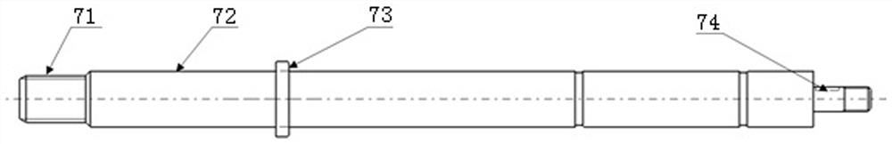
[0033] On the basis of the above-mentioned embodiment, this embodiment further defines the structure of the positioning pin 7, such as figure 2 As shown, the positioning pins 7 are, from left to right, an insertion portion 71 inserted into the fixing hole in the middle of the fixing pin base 1 , an optical axis portion 72 placed in the pressing nut 2 and matched with its hole axis, and the tooth cover 3 . The matching chainring 73 and the driving end 74 that drives the positioning pin 7 to move. The other parts of this embodiment are the same as the above-mentioned embodiments, and are not repeated here.

Embodiment 3

[0035] On the basis of the above-mentioned embodiment, this embodiment further defines the structure of the positioning pin 7, such as figure 1 , 2, the insertion part 71 of the positioning pin 7 is provided with an external thread, the fixing hole in the middle of the fixing pin base 1 is provided with an internal thread, the insertion part 71 of the positioning pin 7 and the fixing hole in the middle of the fixing pin base 1 are threaded connect. The other parts of this embodiment are the same as the above-mentioned embodiments, and are not repeated here.


PUM


Abstract

The invention discloses a fast positioning bolt locking device, which comprises a flange seat provided with an internal thread inside, a pressing nut provided with an external thread on the outside, a positioning pin embedded in the pressing nut, and a fixing pin for fixing the positioning pin. Pin seat, the middle part of the fixed pin seat is provided with a fixing hole, the end is provided with a flange; The flange plate of the pressing nut matches the flange plate at the end of the fixed pin seat, and the other end of the pressing nut placed in the flange seat is provided with a tooth cover; the middle part of the positioning pin is provided with a tooth plate matching the tooth cover. The invention makes up the gap between the tooling equipment and the fixed guide rail platform through the staged engagement and separation of the tooth cover and the tooth plate, and generates a great locking force, which can effectively solve the disadvantages of the traditional positioning method, and achieve fast and convenient locking. Tight positioning action; to avoid bending damage caused by the bolt, resulting in positioning failure, suitable for wide application.

Description

technical field [0001] The invention relates to the technical field of assembling, positioning and locking equipment for aircraft components, in particular to a fast positioning bolt locking device. Background technique [0002] Due to the large dimensions and complex structure of the parts of the aircraft fuselage, in order to adapt to the aircraft structure and ensure the openness of aircraft assembly and processing, the volume and weight of aircraft assembly tooling equipment also increase accordingly. And with the popularization of digital manufacturing and processing, large-scale assembly tooling equipment needs to have the characteristics of production lines, which can be transferred along the fixed guide rails. After the transfer process, the tooling equipment needs to rely on stable and reliable positioning and locking devices to achieve its own positioning. However, because the tooling equipment and the fixed rail platform cannot be closely fitted, resulting in a ce...

Claims


Application Information

Patent Timeline
Patent Type & Authority Patents(China)
IPC IPC(8): F16B35/04F16B37/00F16B37/04
CPCF16B35/041F16B37/00F16B37/041
Inventor 王志乾喻洪松邓珍波
Owner CHENGDU AIRCRAFT INDUSTRY GROUP
Why Eureka
Try Eureka