
An acceleration measurement method based on diamagnetic levitation mechanical system

A technology of acceleration measurement and mechanical system, which is applied in the directions of acceleration measurement, velocity/acceleration/shock measurement, and acceleration measurement using inertial force. , the effect of low parameter noise and high detection efficiency

Active Publication Date: 2022-08-05
NANJING UNIV
View PDF25 Cites 0 Cited by
  • Summary
  • Abstract
  • Description
  • Claims
  • Application Information

AI Technical Summary

Problems solved by technology

[0006] In view of the deficiencies in the prior art, the object of the present invention is to provide a method for measuring acceleration based on the anti-magnetic levitation mechanical system, so as to solve the problems raised in the above-mentioned background technology. By proposing anti-magnetic levitation acceleration, the present invention is different from existing ones in physical principle Some suspension systems, such as optical suspension, electrostatic suspension, superconducting suspension, etc., have the highest absolute sensitivity, and compared with electrostatic suspension and optical suspension, they do not require external energy input, have the lowest parameter noise, and reduce the limit acceleration sensitivity In addition, the proposed anti-magnetic levitation acceleration does not need to rely on the low temperature environment, can independently and effectively reduce the system power consumption, and meets the characteristics of working at room temperature or low temperature environment at the same time, which solves the problems in the prior art

Method used


Image

  • An acceleration measurement method based on diamagnetic levitation mechanical system
  • An acceleration measurement method based on diamagnetic levitation mechanical system
  • An acceleration measurement method based on diamagnetic levitation mechanical system

Examples


Embodiment Construction

[0061] It is easy to understand that, according to the technical solutions of the present invention, without changing the essential spirit of the present invention, those of ordinary skill in the art can propose various alternative structures and implementations. Therefore, the following specific embodiments and accompanying drawings are only exemplary descriptions of the technical solutions of the present invention, and should not be regarded as all of the present invention or as limitations or restrictions on the technical solutions of the present invention.

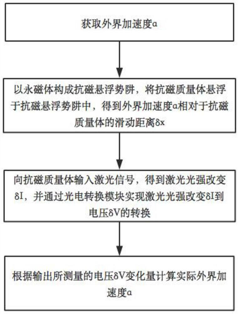
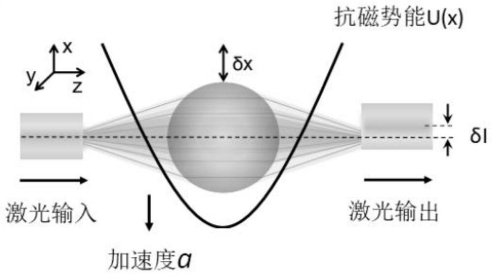
[0062] like Figure 1-2 As shown, as an embodiment of the present invention, the present invention provides a technical solution: an acceleration measurement method based on a diamagnetic suspension mechanics system, comprising the following steps:

[0063] The first step is to obtain the external acceleration a;

[0064] The second step is to build an acceleration-sensitive module

[0065] A diamagnetic levitation p...


PUM


Abstract

The invention provides an acceleration measurement method based on a diamagnetic levitation mechanical system. The method includes the first step of obtaining the external acceleration a; the second step of constructing an acceleration sensitive module, using a magnetic potential well to suspend a diamagnetic mass body to obtain the external acceleration a brought by the The position of the diamagnetic mass body moves δx; the third step is to build a position measurement module to realize the conversion of the laser light intensity change δI to the voltage δV; the fourth step, according to the output measured voltage δV change Calculate the actual external acceleration a. By proposing an anti-magnetic levitation acceleration sensitive method, the present invention is physically different from the existing levitation systems, such as optical levitation, electrostatic levitation, superconducting levitation, etc. Parametric noise, reduce the main noise source limiting acceleration sensitivity, and at the same time, compared with superconducting suspension, it can work in room temperature or low temperature environment.

Description

technical field [0001] The invention relates to the technical field of acceleration measurement, in particular to an acceleration measurement method based on an antimagnetic suspension mechanical system. Background technique [0002] High-precision accelerometers are the core technology for applications such as inertial navigation and gravity measurement. Current accelerometers include cold atom accelerometers, neutron accelerometers, quartz accelerometers, suspension accelerometers, micro-electromechanical systems (MEMS) accelerometers, optical Mechanical accelerometer, optical suspension accelerometer, suspension accelerometer, etc. Among them, the suspension accelerometer has the highest accuracy in principle. Its core is a mass body suspended by an electromagnetic field. According to the general theory of relativity, acceleration will bring about the movement of the position of the suspension body. By measuring this position, the acceleration can be measured. To realize...

Claims


Application Information

Patent Timeline
Patent Type & Authority Patents(China)
IPC IPC(8): G01P15/03G01P15/093
CPCG01P15/03G01P15/093
Inventor 黄璞孔熙
Owner NANJING UNIV
Learn More