Flying probe testing device and rapid positioning device thereof

A positioning device, flying probe testing machine technology, applied in the direction of measuring device, measuring device shell, measuring device magnet, etc., can solve the problems of wrong test position, small pins, large error, etc., and achieve good detection, good fault tolerance rate, and structure simple effect

Inactive Publication Date: 2021-10-08
昆山兢美电子科技有限公司
View PDF0 Cites 0 Cited by
  • Summary
  • Abstract
  • Description
  • Claims
  • Application Information

AI Technical Summary

Problems solved by technology

[0003] The size of the circuit board is small, and the pins to be tested on the circuit board are even smaller, and the positions of each row of pins are different. When testing, because the distance between each pin is very close, when the test device moves a There is a deviation in the unit. After multiple pins are tested, the error will become larger and larger, which will directly lead to the wrong test position, repeated testing or missing problems. Therefore, we need a flying probe test device with a corrective effect and Quick positioning device

Method used


Image

  • Flying probe testing device and rapid positioning device thereof
  • Flying probe testing device and rapid positioning device thereof
  • Flying probe testing device and rapid positioning device thereof

Examples


Embodiment Construction

[0025] The following will clearly and completely describe the technical solutions in the embodiments of the present invention with reference to the accompanying drawings in the embodiments of the present invention. Obviously, the described embodiments are only some, not all, embodiments of the present invention.

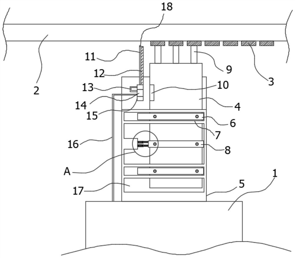
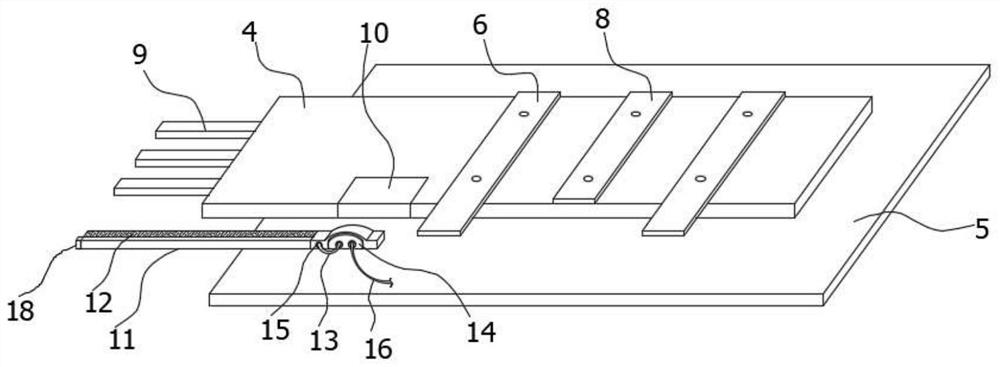
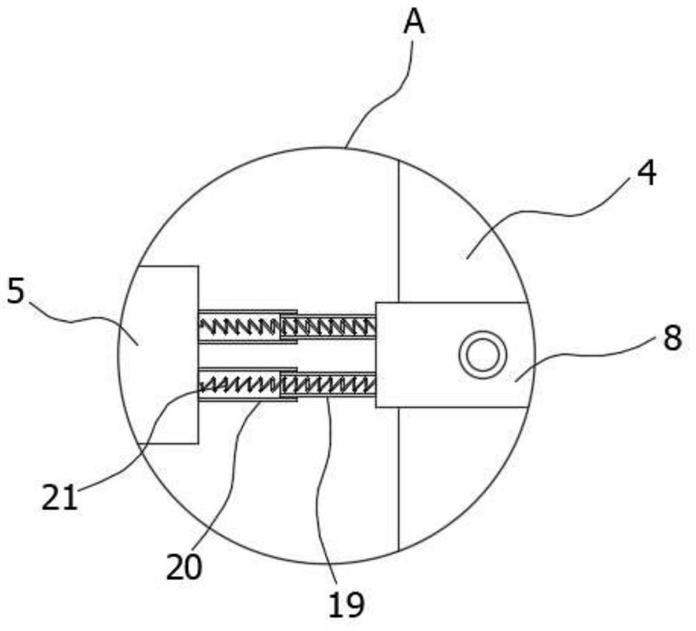
[0026] refer to Figure 1-3 , a flying probe testing device and its rapid positioning device, comprising: a flying probe testing machine body 1 facing a circuit board to be tested 2, the flying probe testing machine body 1 is used to carry the flying probe rapid positioning device, and the flying probe testing One end of the machine body 1 facing the circuit board 2 to be tested is fixedly connected with a base plate 5, and a plurality of component pins 3 to be tested are arranged on the circuit board 2 to be tested; a slidable test circuit board 4 arranged on the upper surface of the base plate 5, The test circuit board 4 is equipped with a plurality of test pins 9 ...


PUM


Abstract

The invention discloses a flying probe testing device and a rapid positioning device thereof. The flying probe testing device comprises a flying probe testing machine body opposite to a to-be-tested circuit board, wherein the flying probe testing machine body is used for bearing the flying probe rapid positioning device, one end of the flying probe testing machine body facing the to-be-tested circuit board is fixedly connected with a bottom plate, and a plurality of element pins needing to be tested are arranged on the circuit board to be tested; a slidable test circuit board which is arranged on the upper surface of the bottom plate, wherein a plurality of test pins used for testing the element pins are mounted at one end, facing the circuit board to be tested, of the test circuit board; and a sliding mechanism which is arranged between the bottom plate and the test circuit board. The device is simple in structure, and has a better error-tolerant rate, so that circuit boards with different designs can be well detected. The error range of the flying probe testing machine can be automatically detected in the pin detection process, so that the data can be provided for device maintenance.

Description

technical field [0001] The invention belongs to the technical field of printed circuit board testing, in particular to a flying probe testing device and a rapid positioning device thereof. Background technique [0002] The flying probe testing machine is used to test the circuit board, which is divided into two categories, one is to test the PCB, and the other is to test the PCBA. 1. An instrument for testing PCB boards (printed circuit boards) with small measuring point distances. It mainly tests the insulation and conduction values ​​of circuit boards. Perform real-time monitoring. [0003] The size of the circuit board is small, and the pins to be tested on the circuit board are even smaller, and the positions of each row of pins are different. When testing, because the distance between each pin is very close, when the test device moves a There is a deviation in the unit time. After multiple pins are tested, the error will become larger and larger, which will directly l...

Claims


Application Information

Patent Timeline
Patent Type & Authority Applications(China)
IPC IPC(8): G01R1/04G01R1/16G01R35/00
CPCG01R1/04G01R1/0408G01R1/16G01R35/005
Inventor 李东影
Owner 昆山兢美电子科技有限公司
Why Eureka
Try Eureka