Infrared image hybrid noise reduction method based on noise recognition
An infrared image and noise technology, applied in the field of infrared image hybrid noise reduction based on noise recognition, can solve problems such as image distortion
- Summary
- Abstract
- Description
- Claims
- Application Information
AI Technical Summary
Problems solved by technology
Method used
Image

Examples
Embodiment Construction
[0037] The specific embodiments of the present invention are described below so that those skilled in the art can understand the present invention, but it should be clear that the present invention is not limited to the scope of the specific embodiments. For those of ordinary skill in the art, as long as various changes Within the spirit and scope of the present invention defined and determined by the appended claims, these changes are obvious, and all inventions and creations using the concept of the present invention are included in the protection list.
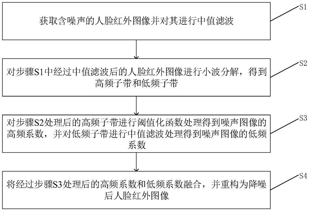
[0038] A hybrid noise reduction method for infrared images based on noise recognition, such as figure 1 shown, including the following steps:
[0039] S1. Acquiring a noise-containing human face infrared image and performing median filtering on it;
[0040] In this embodiment, step S1 specifically includes:
[0041] S11. Construct an n×n filter kernel and use the constructed filter kernel to slide on the acquired face inf...
PUM
 Abstract
Description
Claims
Application Information
 - R&D
- Intellectual Property
- Life Sciences
- Materials
- Tech Scout
- Unparalleled Data Quality
- Higher Quality Content
- 60% Fewer Hallucinations
Browse by: Latest US Patents, China's latest patents, Technical Efficacy Thesaurus, Application Domain, Technology Topic, Popular Technical Reports.
© 2025 PatSnap. All rights reserved.Legal|Privacy policy|Modern Slavery Act Transparency Statement|Sitemap|About US| Contact US: help@patsnap.com