Cutting and grinding device for cylindrical steel

A cutting and grinding, cylindrical technology, applied in the direction of feeding devices, other manufacturing equipment/tools, metal processing machinery parts, etc., can solve the problems of operator danger, affecting later use, rust on the surface of steel, etc., to prolong the service life , Guarantee safety and improve the effect of construction safety

Pending Publication Date: 2021-10-12
杭州显妙贸易有限公司
View PDF0 Cites 0 Cited by
  • Summary
  • Abstract
  • Description
  • Claims
  • Application Information

AI Technical Summary

Problems solved by technology

[0006] Aiming at the deficiencies of the prior art, the present invention provides a cutting and grinding device for cylindrical steel, which has the advantages of rust removal and stall protection on the steel surface, and solves the problem of storing steel in the open under normal circumstances, so that in rainy and snowy weather It will cause rust on the surface of the steel, which will directly affect the later use. In order to ensure the normal construction, the steel needs to be processed twice to remove the rust on the steel surface before it can be used normally. In most cases, they are in the shape of straight strips or discs, which are not suitable for direct use. The steel needs to be cut in sections. If the speed is too fast during the cutting process, it will be very dangerous to the operator.

Method used


Image

  • Cutting and grinding device for cylindrical steel
  • Cutting and grinding device for cylindrical steel
  • Cutting and grinding device for cylindrical steel

Examples


Embodiment Construction

[0026] The following will clearly and completely describe the technical solutions in the embodiments of the present invention with reference to the accompanying drawings in the embodiments of the present invention. Obviously, the described embodiments are only some, not all, embodiments of the present invention. Based on the embodiments of the present invention, all other embodiments obtained by persons of ordinary skill in the art without making creative efforts belong to the protection scope of the present invention.

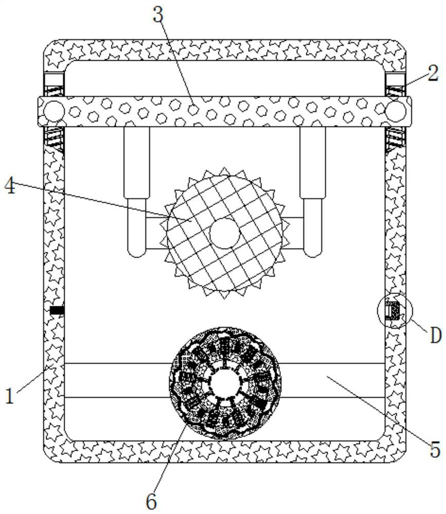
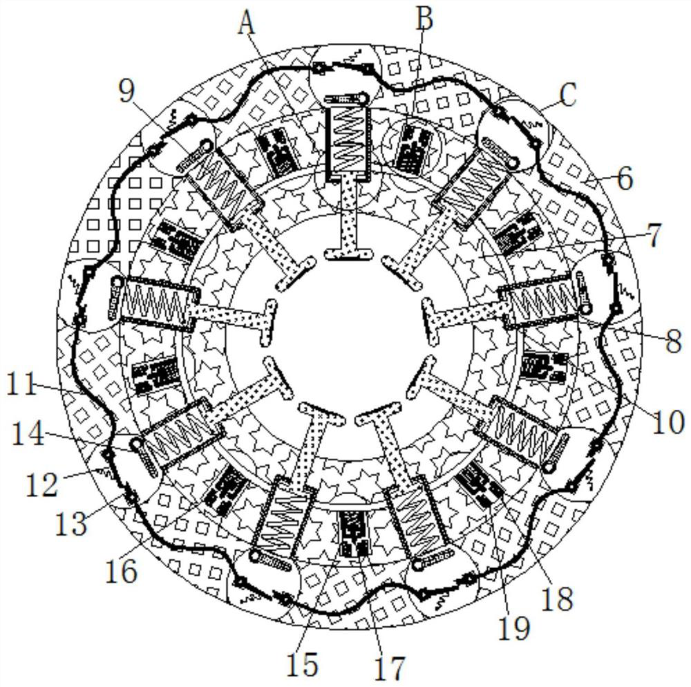
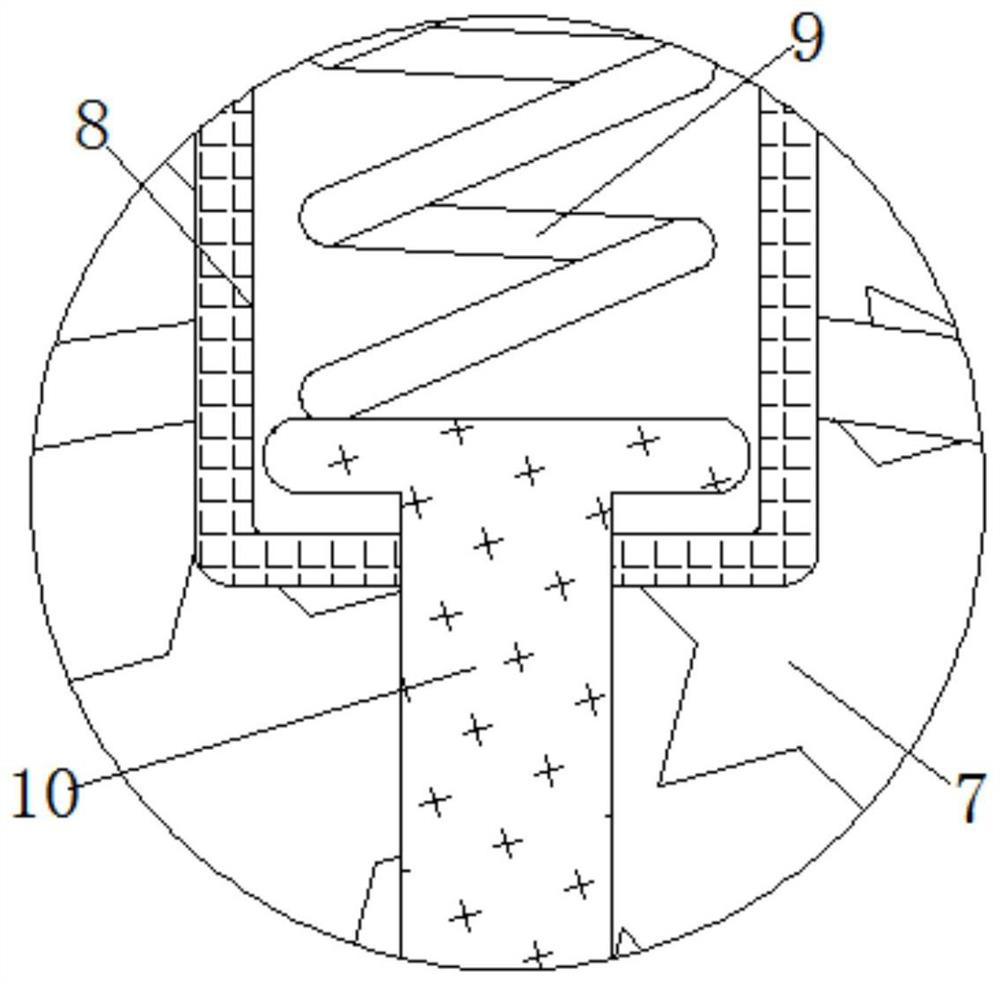
[0027] see Figure 1-6 , a cutting and grinding device for cylindrical steel, comprising a frame 1, the inside of the frame 1 is rotatably connected with a screw rod 2, the inside of the frame 1 is movably connected with a moving rod 3, and the inside of the moving rod 3 is fixedly connected with a groove, the concave The specifications and positions of the grooves all match the specifications and positions of the screw rod 2, the grooves are threadedly connec...


PUM


Abstract

The invention relates to the technical field of electromechanical equipment, and discloses a cutting and grinding device for cylindrical steel. The cutting and grinding device comprises a frame, a screw rod is rotatably connected inside the frame, a moving rod is movably connected inside the frame, a cutter is movably connected inside the frame, a fixed rod is fixedly connected inside the frame, an outer shell is movably connected outside the fixed rod, and a rotating shaft is rotationally connected inside the outer shell. Through mutual cooperation of the screw rod, the moving rod, the cutter, a photoresistor, the rotating shaft, a buffer spring and a grinding rod, the device can automatically stop moving at the corresponding position when cutting steel, the steel can be accurately cut, rust on the surface of the steel can be ground away, in this way, the device can be conveniently used by constructors, and the service life of the steel can be greatly prolonged, so that the effects of automatically cutting and automatically removing rust on the surface of the steel are achieved.

Description

technical field [0001] The invention relates to the technical field of electromechanical equipment, in particular to a cutting and grinding device for cylindrical steel. Background technique [0002] Steel is an essential and important material for national construction and the realization of the four modernizations. It is widely used and has a variety of varieties. According to the different cross-sectional shapes, steel is generally divided into four categories: profiles, plates, pipes and metal products. With the application of steel now It is becoming more and more widespread, and more and more steel materials are used in some landmark buildings or tourist playgrounds. [0003] Among them, the range of cylindrical steel is also very wide. After the steel is manufactured, it will be transported to the required site. However, because the traditional method makes the steel occupy a large area, it is generally stored in the open air. Rainy and snowy weather will cause rust ...

Claims


Application Information

Patent Timeline
Patent Type & Authority Applications(China)
IPC IPC(8): B23P23/04B23Q5/28
CPCB23P23/04B23Q5/28
Inventor 胡心怡
Owner 杭州显妙贸易有限公司
Why Eureka
Try Eureka