Material burying device

A workpiece and hot-melt technology, applied in the field of mechanical processing, can solve the problems of increasing the labor intensity of operators, low production efficiency, and high cost

Pending Publication Date: 2021-10-12
FU DING ELECTRONICSAL TECH JIASHAN
View PDF2 Cites 0 Cited by
  • Summary
  • Abstract
  • Description
  • Claims
  • Application Information

AI Technical Summary

Problems solved by technology

[0003] In the prior art, manual operation is generally used, and its production efficiency is low, the cost is high, and the labor intensity of the operators is increased.

Method used


Image

  • Material burying device
  • Material burying device
  • Material burying device

Examples


Embodiment Construction

[0093] The following will clearly and completely describe the technical solutions in the embodiments of the present invention with reference to the accompanying drawings in the embodiments of the present invention. Obviously, the described embodiments are only examples of the present invention, rather than exhaustive. Based on the embodiments of the present invention, all other embodiments obtained by persons of ordinary skill in the art without making creative efforts belong to the protection scope of the present invention.

[0094] It should be noted that when an element is considered to be "connected" to another element, it may be directly connected to the other element or there may be an intervening element at the same time. When an element is referred to as being "disposed on" another element, it can be directly disposed on the other element or an intervening element may also exist.

[0095]Unless otherwise defined, all technical and scientific terms used herein have the ...


PUM


Abstract

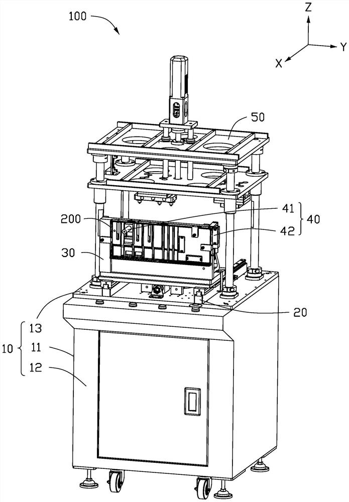
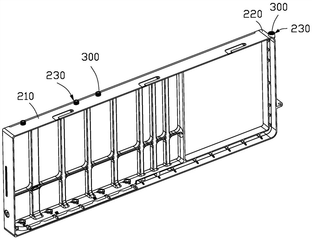
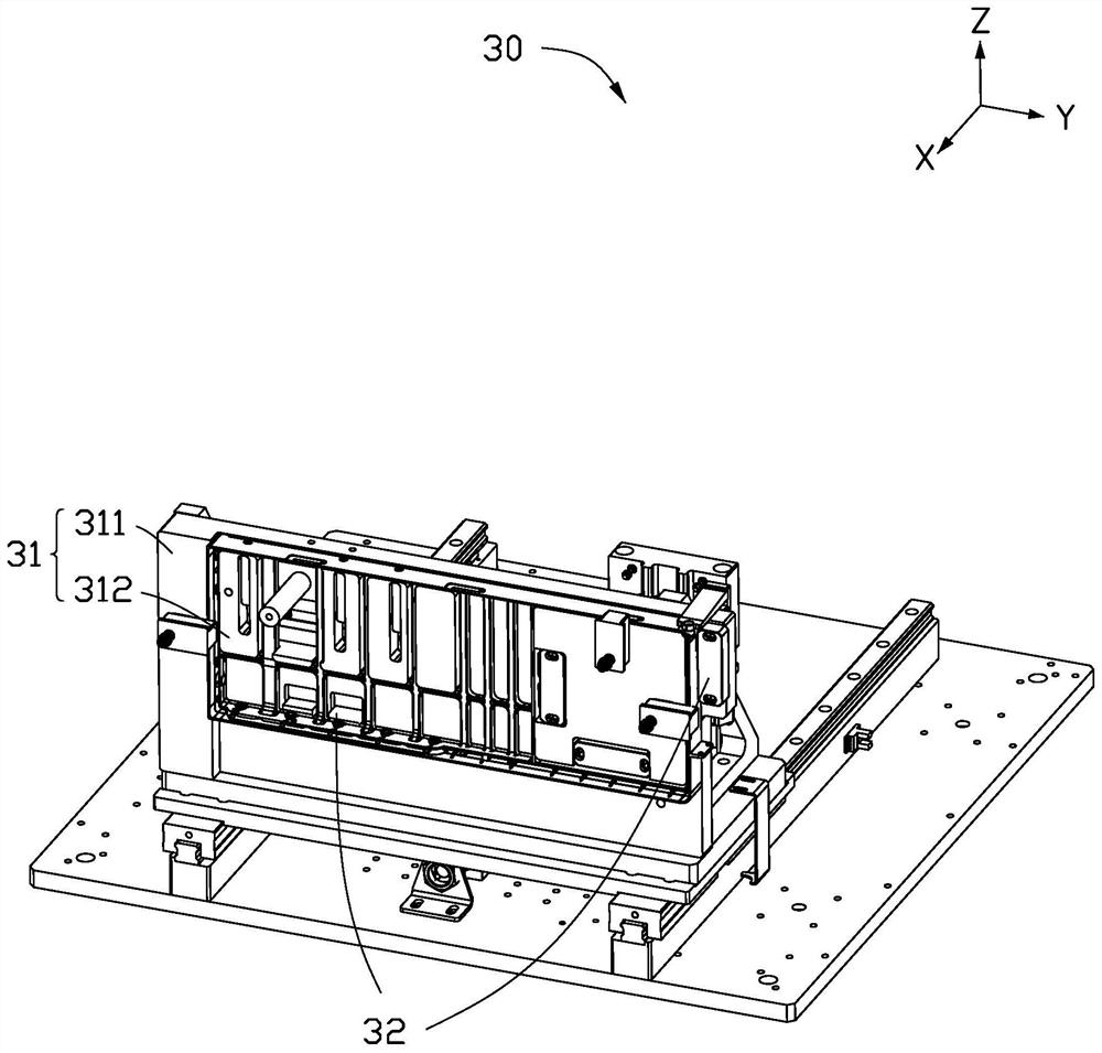
The invention provides a material burying device. The material burying device comprises a workbench, a positioning mechanism arranged on the workbench and comprising a hanging piece used for hanging a first workpiece, an abutting piece used for abutting against the inner side face and the outer side face of the first workpiece, a pressing piece used for pressing the first workpiece, a hot melting mechanism arranged on the workbench, located above the positioning mechanism, and comprising at least one hot melting piece used for heating a second workpiece, and a hot melting driving part connected with the hot melting part and used for driving the hot melting part to move towards the positioning mechanism, so that the hot melting part is in contact with and heats the second workpiece, and the second workpiece is buried in a fixing hole of the first workpiece. The material burying device is simple in structure, convenient to operate, high in material burying efficiency, and capable of reducing the cost.

Description

technical field [0001] The invention relates to the field of machining, in particular to a material embedding device. Background technique [0002] At present, parts need to be buried in the fixing holes on the side of many electronic products. At this time, it is necessary to adopt the method of hot-melt embedding, grab and install the parts in the fixing holes of the product, and perform hot-melt embedding. [0003] In the prior art, manual operation is generally adopted, and the production efficiency is low, the cost is high, and the labor intensity of the operators is increased. Contents of the invention [0004] Based on this, it is necessary to propose a material embedding device with simple operation and high material embedding efficiency to solve the above problems. [0005] The present invention proposes a material embedding device, comprising: [0006] workbench; [0007] The positioning mechanism is arranged on the workbench, and includes: a hanging part for ...

Claims


Application Information

Patent Timeline
IPC IPC(8): B29C65/44B29C65/78
CPCB29C65/44B29C65/7841B29C65/7858
Inventor 王治民刘春笋杜长林高学俊张成黄志祥
Owner FU DING ELECTRONICSAL TECH JIASHAN
Why Eureka
Try Eureka