
Toggle type punch press

A toggle-type punching technology, applied in the field of toggle-type punching machines, can solve the problems of weak connecting rod tightening force, weakened power transmission, slow moving speed, etc., to save costs and solve cumbersome effects.

Inactive Publication Date: 2021-10-12
赵珠显
View PDF10 Cites 0 Cited by
  • Summary
  • Abstract
  • Description
  • Claims
  • Application Information

AI Technical Summary

Problems solved by technology

[0006] The disadvantage of the existing toggle punch is that although the moving speed of the slider is slow when it is lowered, it does not reach the level of improving the molding quality, and the moving speed of the slider when it is not related to the molding quality is also slowed down and increased. Overall operating time, resulting in reduced productivity
[0007] And, the shortcoming of existing toggle punch press is that the operation of connecting link and link mechanism requires too wide operating space
[0008] In addition, in the operation structure of the connecting link and the eccentric block of the conventional toggle punch press, the connecting link connected to the eccentric shaft is fastened on only one side, so the fastening force based on the connecting link is weak, and it will be damaged when used for a long time. Weakening of power transmission due to weakening of the fastening force of the connecting link connected to the eccentric shaft
[0009] In addition, according to the existing toggle punch press, the crankless toggle mechanism consisting of the upper link, the lower link, and the plunger that supports the up and down reciprocating movement of the bar screw has wear and tear on the fastened part of the bar screw and the plunger. And the cumbersome need to replace the plunger

Method used


Image

  • Toggle type punch press
  • Toggle type punch press
  • Toggle type punch press

Examples


Embodiment Construction

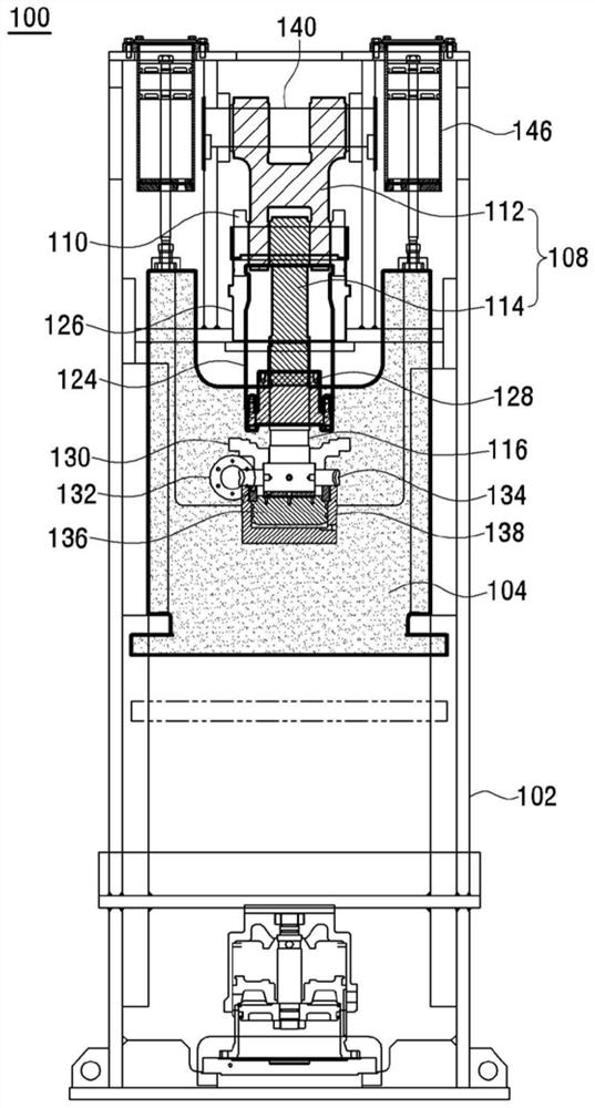
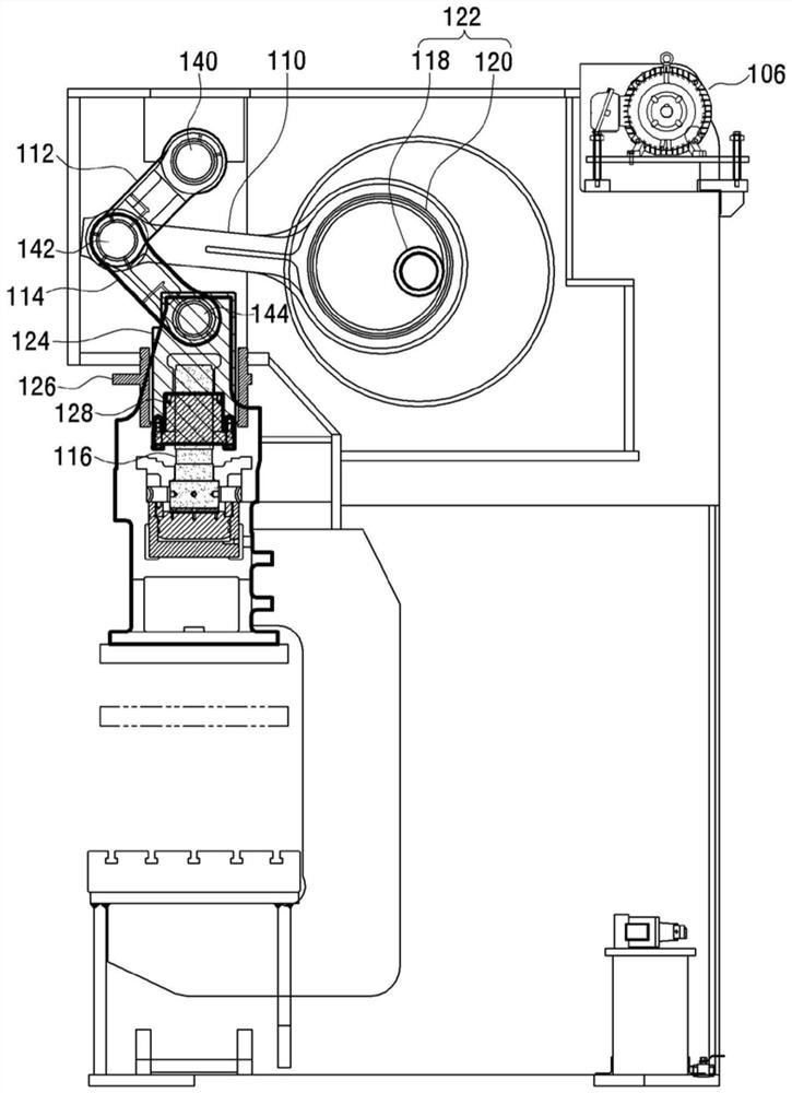
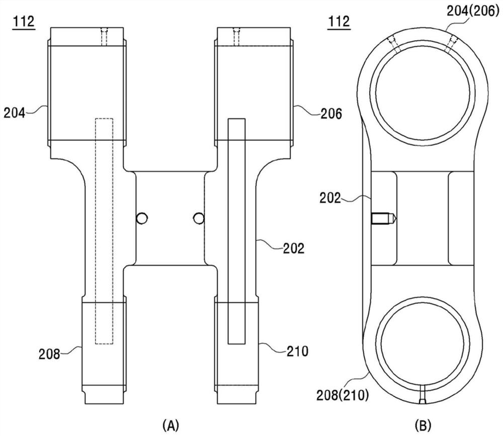
[0047] Hereinafter, the structure and functional effects of the toggle punch press of the present invention will be described with reference to the accompanying drawings.

[0048] The detailed description of specific embodiments shown in the drawings should be read in conjunction with the accompanying drawings, which are only to be considered as part of the entire specification. The description of direction or directionality is for convenience of explanation only, and is not intended to limit the scope of rights of the present invention in any way.

[0049] Specifically, terms denoting position such as "lower, upper, horizontal, vertical, upper, lower, upward, downward, upper, lower" or derivatives of these (e.g., "horizontal, downward, "upward", etc.) should be understood with reference to both the described drawings and the related description. In particular, these relative terms are for convenience of description only and do not require a particular orientation in which th...


PUM


Abstract

The invention relates to a toggle type punch press, and in particular to a toggle type punch press in which the load distribution of a drive unit is uniform, stable power transmission is achieved, and consumable replacement is achieved by combining a plunger with a replaceable adjustment nut. The toggle type punch press is characterized in that the upper end of an upper link and the lower end of a lower link are rotatably connected to an upper link pin and a lower link pin correspondingly, and the lower end of the upper link, the upper end of the lower link, and one end of a connecting link are rotatably connected to a center link pin correspondingly; and the connection link is composed of a link ring part with one end connected to the center link pin, an eccentric ring part with the other end connected to an eccentric part, and a rod part connecting the link ring part and the eccentric ring part, the link ring part is composed of a first link ring part and a second link ring part of a symmetrical structure, and the eccentric ring part is composed of a first eccentric ring part and a second eccentric ring part of a symmetrical structure.

Description

technical field [0001] The present invention relates to a toggle punch, and more specifically, to a toggle punch in which the load of the driving part is distributed uniformly and stable power transmission is realized, and the plunger is combined with a replaceable adjusting nut to realize replacement of consumables. Background technique [0002] Among the mechanical punching machines, the toggle punching machine is generally suitable for precision compression processing, embossing, extrusion, forging, etc. because the upper die touches the lower die softly for a long time when the product is punched. [0003] A toggle punch press is also called a toggle punch press, which has a frame, a liftable slider mounted on the frame, and a driving device for generating and applying a driving force to lift the slider. [0004] The driving device has a motor arranged on the frame, a flywheel connected to the motor through a belt, a connecting link connected to the flywheel at one end a...

Claims


Application Information

Patent Timeline
Patent Type & Authority Applications(China)
IPC IPC(8): B30B1/14B30B15/00
CPCB30B1/14B30B15/00
Inventor 赵珠显
Owner 赵珠显
Learn More