Trolley with air injection auxiliary power mechanism and control method thereof

A technology of auxiliary power and power mechanism, which is applied in the direction of motor vehicles, power devices, vehicle parts, etc., and can solve problems such as difficulty in improving maneuverability, difficulty in ensuring chassis stability, and low grip

Active Publication Date: 2021-10-12
TIANJIN UNIV
View PDF8 Cites 0 Cited by
  • Summary
  • Abstract
  • Description
  • Claims
  • Application Information

AI Technical Summary

Problems solved by technology

[0004] The present invention provides a trolley with an air-jet auxiliary power mechanism and its control method to solve the difficulty in improving the maneuverability, and the grip is too small and the stability of the chassis Difficult to guarantee

Method used


Image

  • Trolley with air injection auxiliary power mechanism and control method thereof
  • Trolley with air injection auxiliary power mechanism and control method thereof
  • Trolley with air injection auxiliary power mechanism and control method thereof

Examples


Embodiment 1

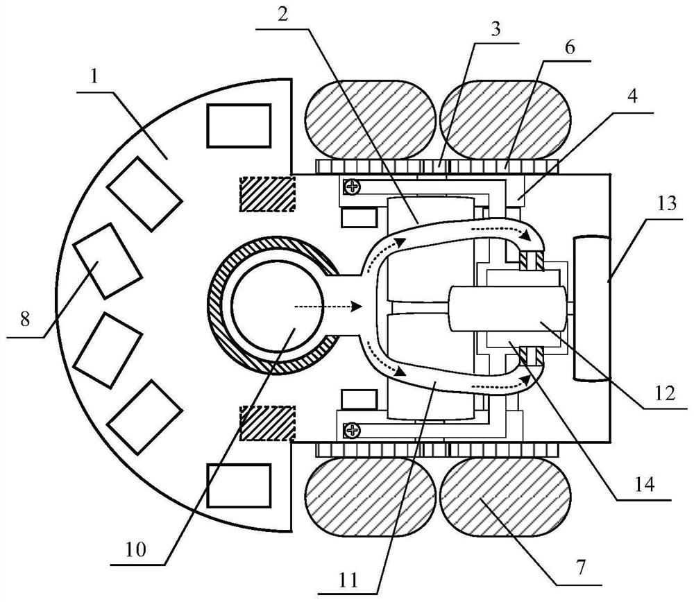
[0028] like figure 1 Shown is a top view of a robot car equipped with an air jet auxiliary power mechanism, which is composed of four parts: a control circuit board 1, a drive mechanism, a vision mechanism and an auxiliary power mechanism. The control circuit board 1 also serves as the chassis of the robot, and is provided with through holes. The power mechanism includes main motor 2, transmission gear 3, wheel hub bracket 4, metal bearing 5, wheel hub 6 and tire cover 7. There are two main motors 2 and are located above the control circuit board, transmission gear 3, wheel hub bracket 4, wheel hub 6 and Tire cover 7 is positioned at control circuit board both sides. The visual mechanism includes six groups of digital infrared sensors 8 that are independently arranged and do not interfere with each other, and are installed on the front side of the control circuit board. Among them, each group of digital infrared sensors includes an infrared emitting tube and an infrared rece...

Embodiment 2

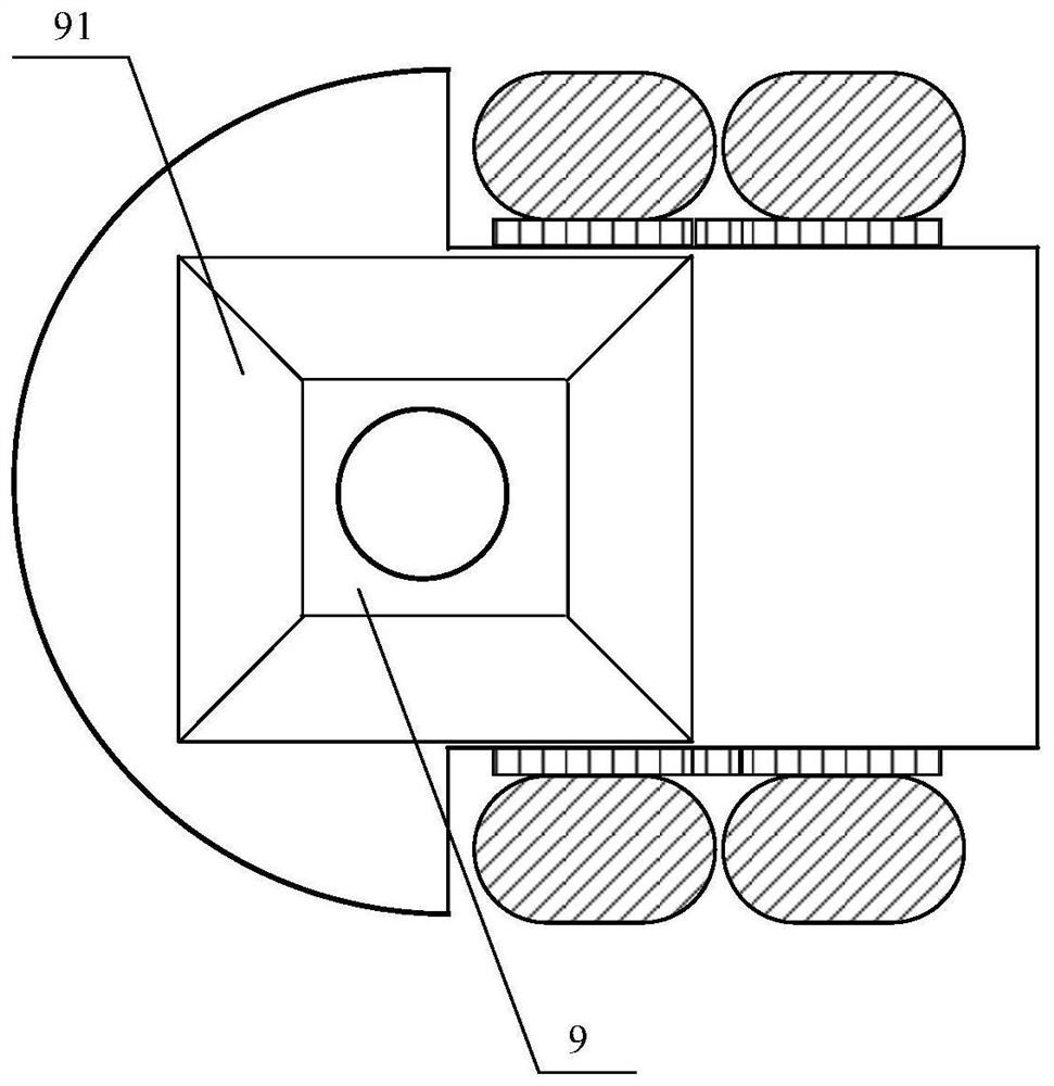
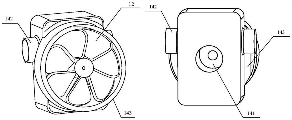
[0040] like Figure 4 Shown is a top view of a robot car equipped with an air jet auxiliary power mechanism, which is composed of four parts: a control circuit board 1, a drive mechanism, a vision mechanism and an auxiliary power mechanism. Among them, the driving mechanism and visual mechanism are exactly the same as Case 1. The control circuit board 1 also serves as the chassis of the robot, and is provided with two through holes on the left and the right. The auxiliary power mechanism includes a semi-closed cavity 9 under the plate, an air suction cavity 10 on the plate, an air delivery pipe 11, a fan motor 12, a pneumatic fan blade 13 and an air injection cavity 14. There are two air injection chambers 14, each equipped with a fan motor 12 and a pneumatic fan blade 13 separately. The air pumping chamber 10 on the board has two chambers in total, and the air conveying pipe 11 has two paths in total, including a left conveying pipe and a right conveying pipe. A jet chambe...


PUM


Abstract

The invention relates to a trolley with an air injection auxiliary power mechanism. The trolley comprises a power mechanism for driving a hub and a tire sleeve, and an air injection auxiliary power mechanism, wherein the power mechanism comprises a main motor; the trolley is characterized in that, the air injection auxiliary power mechanism comprises a chassis with a through-hole, an air suction cavity arranged at the through-hole of the chassis, an air conveying pipe, a fan motor, pneumatic fan blades, and an air injection cavity, wherein an air injection hole is formed in the rear part of the air injection cavity, the pneumatic fan blades are arranged at the rear part of the air injection cavity, the air injection cavity is driven by the fan motor, the pneumatic fan blades suck air below a plate into the air suction cavity from the chassis through-hole, and then the air enters the air injection cavity through the air conveying pipe and is sprayed out from the air injection hole, so that the trolley is tightly attached downwards under the action of atmospheric pressure, and the counter-acting force brought by backward air injection plays a role of auxiliary power on the trolley. The invention further provides a control method of the air injection auxiliary power mechanism of the trolley.

Description

technical field [0001] The invention relates to an air injection auxiliary power mechanism for a trolley and a control method thereof. Background technique [0002] In recent years, the software and hardware technology of the robot car has received more and more attention in competitions, teaching and scientific research. On the one hand, the application of robot cars can be expanded to search and rescue in unknown environments, robot path planning, high-speed motion control, and automatic driving. At the same time, it can also provide a multi-level and comprehensive basic platform for college students, makers, technology enthusiasts, etc. to carry out artificial intelligence learning and training. [0003] In order to increase the moving speed of the trolley, the weight of the existing robot trolleys is generally strictly limited, but this also brings about the problem that the grip of the tires is too small and the stability of the chassis is difficult to guarantee. In o...

Claims


Application Information

Patent Timeline
Patent Type & Authority Applications(China)
IPC IPC(8): B62D63/02B62D63/04B60K8/00B60R16/02
CPCB62D63/02B62D63/04B60K8/00B60R16/02
Inventor 刘迎澍程果刘赫王磊
Owner TIANJIN UNIV
Why Eureka
Try Eureka