Automatic adjustment frame precision detection device and frame detection reference determination method

A precision detection and automatic adjustment technology, applied in the direction of measuring devices, mechanical measuring devices, mechanical devices, etc., can solve the inconvenience of frame precision adjustment and vehicle problem analysis, and many welds at the joint between the flange of the lower swing arm and the longitudinal beam , Can not truly reflect the welding accuracy of the frame and other issues, to achieve the effect of eliminating the difficulty of position adjustment, low cost, and lightweight design

Active Publication Date: 2021-10-12
郑州日产汽车有限公司
View PDF11 Cites 2 Cited by
  • Summary
  • Abstract
  • Description
  • Claims
  • Application Information

AI Technical Summary

Problems solved by technology

[0002] In the production of non-bearing frame, since the frame uses CO 2 Welding, the welding deformation of the long-welded parts is large, and the deviation of the parts used as the detection reference during the frame inspection often causes data distortion in the detection of the entire frame due to the deviation caused by the welding deformation.
[0003] At present, the flange of the lower swing arm on the front suspension of the frame is used as the detection benchmark. Since there are many welds at the joint between the flange of the lower swing arm and the longitudinal beam, welding deformation is very easy to occur and the detection of the entire frame is distorted.
Therefore, it is impossible to truly reflect the welding accuracy of the frame, which brings inconvenience to the adjustment of the frame accuracy and the analysis of vehicle problems, and it is difficult to confirm the production consistency of the frame

Method used


Image

  • Automatic adjustment frame precision detection device and frame detection reference determination method
  • Automatic adjustment frame precision detection device and frame detection reference determination method
  • Automatic adjustment frame precision detection device and frame detection reference determination method

Examples


Embodiment Construction

[0035] The specific implementation manners of the present invention will be described in detail below in conjunction with the accompanying drawings.

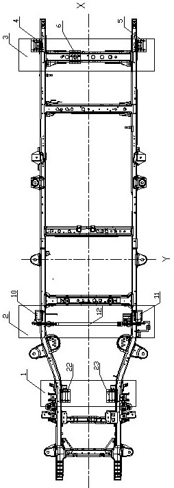
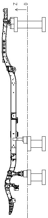
[0036] like Figure 1 to Figure 8 As shown, the automatic adjustment frame accuracy detection device of this embodiment includes a front base 1 , a middle base 2 and a rear base 3 arranged in sequence along the front and rear directions of the frame.

[0037] The left / right fixed support block 4 / 5 and the middle adjustment locator 6 on the rear base 3, the adjustment locator 6 is composed of an adjustment guide rail 7, a fixed pin seat 8 and a positioning pin 9, and the positioning pin 9 is installed on the fixed pin On the seat 8, the fixed pin seat 8 is slidably connected on the adjustment guide rail 7, and the adjustment guide rail 7 is installed on the rear base 3 along the front-rear direction.

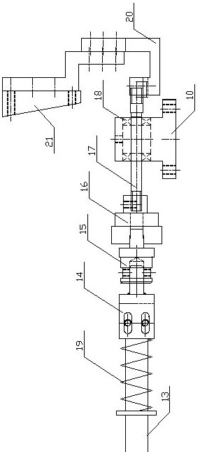
[0038] The middle base 2 is symmetrically provided with a left / right adjustment mechanism, and the left / right adjustment mechani...


PUM


Abstract

The invention discloses an automatic adjustment frame precision detection device and a frame detection reference determination method. The automatic adjustment frame precision detection device comprises a front base, a middle base and a rear base which are sequentially arranged in the front-back direction of a frame; a left / right fixed supporting block and a middle adjusting positioner are mounted on the rear base; a left adjusting mechanism and a right adjusting mechanism are symmetrically arranged on the middle base and connected with the two ends of the flexible adjusting synchronizing shaft respectively; and a left / right rotary movable supporting table is mounted on the front base. The problem of detection precision distortion caused by detection reference deviation due to large frame welding deformation is solved, the consistency and accuracy of frame detection precision are greatly improved, the method can be applied to detection of frames with different widths, the work of replacement, adjustment, detection and positioning is reduced, and the detection efficiency is improved; and the device has the advantages of being high in detection accuracy, exquisite in mechanism, reliable in use and low in cost.

Description

technical field [0001] The invention relates to the technical field of automobile processing and manufacturing, in particular to an automatic adjustment frame precision detection device and a frame detection reference determination method. Background technique [0002] In the production of non-bearing frame, since the frame uses CO 2 Welding, the welding deformation of the long welded parts is large, and the deviation of the parts used as the detection reference during the frame inspection due to the welding deformation often causes data distortion in the detection of the entire frame. [0003] At present, the lower swing arm flange of the front suspension on the frame is used as the detection benchmark. Since there are many welds at the joint between the lower swing arm flange and the longitudinal beam, welding deformation is very easy to occur, which will lead to distortion of the entire frame detection. Therefore, it cannot truly reflect the welding accuracy of the frame...

Claims


Application Information

Patent Timeline
Patent Type & Authority Applications(China)
IPC IPC(8): G01B21/00G01B5/00
CPCG01B21/00G01B5/0002G01B5/0004G01B5/0025Y02T10/40
Inventor 王建华朱鹏德马莲琴范兆博姜国磊孙红辉李建忠王新宇施素玲吴荣张高鹏孟盟田杰英王蒙孔德璐
Owner 郑州日产汽车有限公司
Why Eureka
Try Eureka