Metal part machining equipment capable of automatically collecting materials

A technology for automatic material collection and processing equipment, which is applied in the direction of metal processing equipment, casting equipment, manufacturing tools, etc. It can solve the problems that processing equipment cannot automatically receive materials, and achieve the effects of avoiding scattering, flexibly adjusting the position, and increasing the opening area

Pending Publication Date: 2021-10-15
施俊峰
View PDF9 Cites 0 Cited by
  • Summary
  • Abstract
  • Description
  • Claims
  • Application Information

AI Technical Summary

Problems solved by technology

[0010] The purpose of the present invention is to provide a metal parts processing equipment that automatically collects materials, so as to overcome the problem that the existing metal parts processing equipment cannot automatically receive materials

Method used


Image

  • Metal part machining equipment capable of automatically collecting materials
  • Metal part machining equipment capable of automatically collecting materials
  • Metal part machining equipment capable of automatically collecting materials

Examples


Embodiment 1

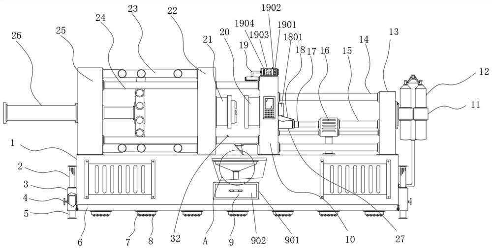
[0041] Example 1: See Figure 1-7 A metal parts processing apparatus, including the cabinet 1, and the top of the casing 1 is provided with a mutually mounted left processing unit, and the left processing unit and the right machining unit are connected by two sets of sliding rods. A automatic receiving device is also provided between the portion and the right machining unit, and the automatic receiving device includes a collecting box 31 and a collecting plate 32, a tank 31 is a tank 1, and a tank 1 of the left opening, and the collecting box 31 The upper surface of the casing 1 is fixed to the upper surface of the box, and the upper left side opening of the collecting box 31 is inclined to the right, and the upper surface of the collecting plate 32 is provided with a sponge pad 33 on the inner surface of the collecting box 31. The plate 32 is hinged to the lower edge of the left opening of the collecting box 31, and the upper portion of the collecting plate 32 is connected to the ...

Embodiment 2

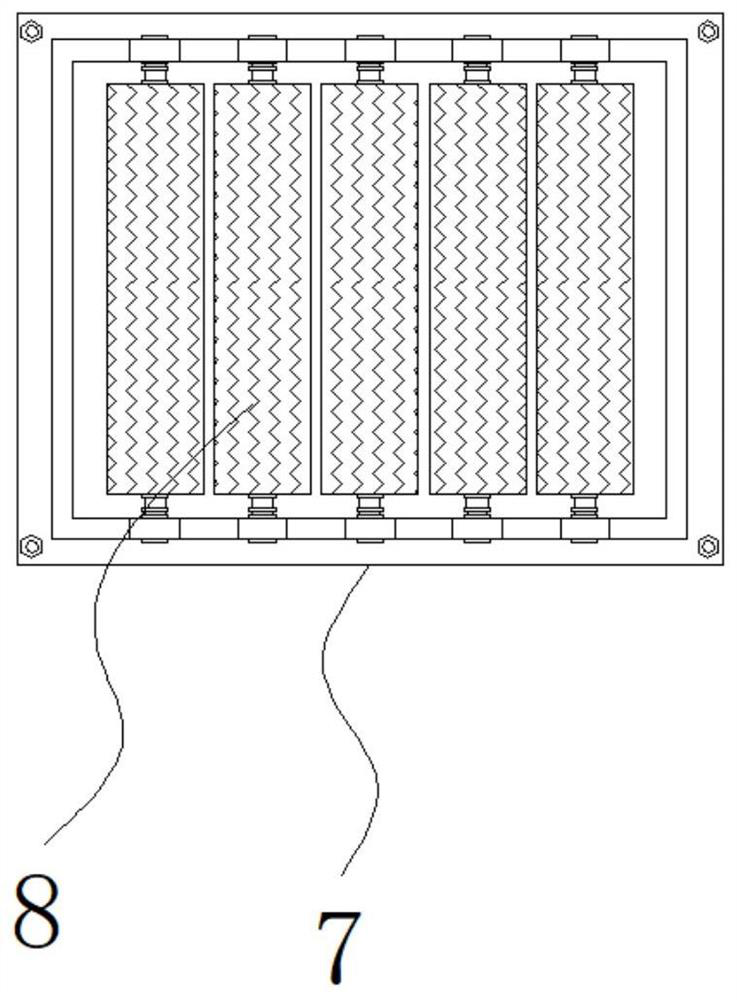
[0043] Example 2: See Figure 1-7 The position adjustment mechanism includes a bottom plate 6, and the bottom plate 6 is fixedly coupled to the bottom end of the casing 1, and the two sides of the bottom plate 6 are fixedly connected to the fixed sleeve 3, respectively, and the top end of the fixed sleeve 3 is fixedly connected to the first hydraulic cylinder 2, which The specific model of the first hydraulic cylinder 2 can be SC150 * 500, and the inside of the fixing sleeve 3 is provided with a support pin 5, and the bottom end of the first hydraulic cylinder 2 extends to the inside of the fixed sleeve 3 and fixed to the top of the support foot 5. The connection, the side of the fixed sleeve 3 is inserted with a fixed hand wheel 4, and the bottom end of the bottom plate 6 is fixedly connected to the plurality of sets of fixed block 7, and the internal activity of the bottom end of the fixed block 7 has a five-component sliding roller 8;

[0044] The fixing block 7 is arranged as a...

Embodiment 3

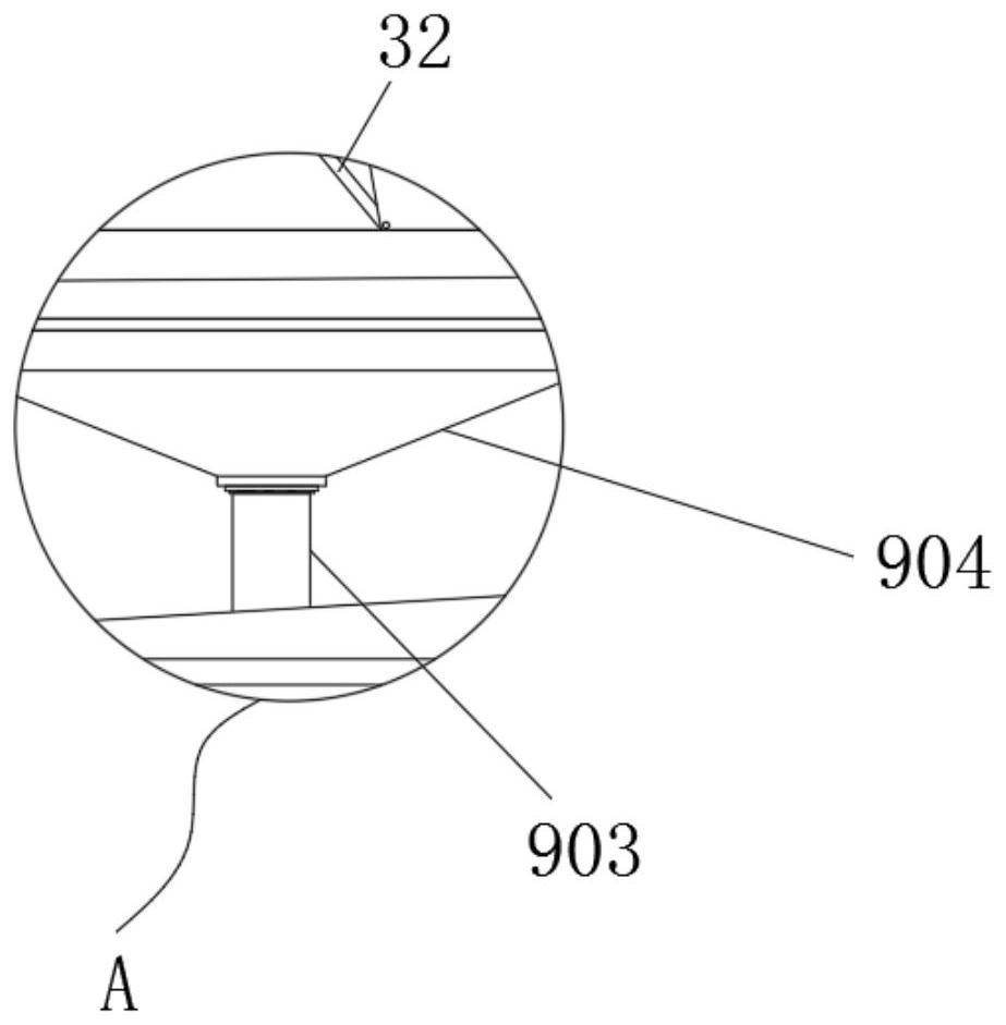
[0046] Example 3: The bottom end of the casing 1 is provided with a dropping collecting structure 9, and the drip collection structure 9 is composed of a fixed groove 901, a reservoir drawer 902, a conduit 903, and a concentrate funnel 904, and the fixed slot 901 is disposed in the casing. 1 The bottom of the inside, the inside of the fixed slot 901 is inserted with a reservoir drawer 902, and the liquid funnel 904 is fixedly attached to the top end of the interior of the casing 1, and the top end of the fixed slot 901 and the bottom end of the collector funnel 904 are fixedly connected. There is a catheter 903;

[0047] The liquid funnel 904 penetrates through the top end of the box 1 and extends to the outside, and the top end of the collector funnel 904 is lower than the bottom end of the sliding retention seat 22, and the internal communication between the conduit 903 and the fixed slot 901;

[0048] Specifically, such as figure 1 with image 3 As shown, when the machine starts...


PUM


Abstract

The invention discloses a metal part machining equipment capable of automatically collecting materials. The metal part machining equipment comprises a box body, the top of the box body is provided with a left machining part and a right machining part which matching with each other, the left machining part and the right machining part are connected through two sliding rods, an automatic material collecting device is further arranged between the left machining part and the right machining part, the automatic material collecting device comprises a material collecting box and a material collecting plate, the material collecting box is a box body with openings in the top and the left side, the material collecting box is fixedly installed on the upper surface of the box body, the material collecting plate is installed on the lower edge of the opening in the left side of the material collecting box in a hinged mode, and the upper portion of the material collecting plate is connected to the material collecting box through a connecting piece. According to the metal part machining equipment, the defects in the prior art are overcome, and metal parts falling between a male die and a female die can be automatically collected.

Description

Technical field [0001] The present invention relates to the technical field of metal product processing equipment, and is specifically belonging to an automatic contained metal parts processing equipment. Background technique [0002] Metal product products are widely used in their high-precision, high toughness, and high performance in electronics, automotive, motor, home appliances, and some communication industries, large aircraft, ships, etc., are often commonplace of metal products. With the continuous development of technology, the die-casting equipment of metal products is also constantly improving, and the traditional die casting machine has a defect, and has to be improved. [0003] In the process of implementing the invention, the inventors have found that there is at least the following problems in the prior art without being resolved: [0004] (1) Traditional metal parts processing equipment, the overall weight is large, and once it is difficult to adjust the position...

Claims


Application Information

Patent Timeline
Patent Type & Authority Applications(China)
IPC IPC(8): B22D17/20B22D45/00
CPCB22D17/20B22D17/2084B22D17/2007B22D17/2038B22D45/005
Inventor 施俊峰
Owner 施俊峰
Why Eureka
Try Eureka