Double-face machining process for annular workpiece for automobile motor
A ring-shaped workpiece, double-sided processing technology, applied in the direction of machine tools suitable for grinding workpiece planes, grinding workpiece supports, metal processing equipment, etc., can solve the problem of inconsistent grinding accuracy of the two sides of the ring workpiece
- Summary
- Abstract
- Description
- Claims
- Application Information
AI Technical Summary
Problems solved by technology
Method used
Image
Examples
Embodiment 1
[0065] Such as figure 1 Shown, a kind of circular workpiece double-sided processing technique for automobile motor is characterized in that, comprises the following steps:
[0066] Step 1, the workpiece is loaded, and the ring-shaped workpiece 10 is sleeved on the loading tray 41 in the loading mechanism 4 installed on the top of the processing table 1;
[0067] Step 2, workpiece centering, the electric spindle 43 located under the loading tray 41 drives the loading tray 41 to rotate, and the centering column 423 in the centering assembly 42 installed under the loading tray 41 is along the waist of the loading tray 41 The outward expansion of the shaped groove 413 interferes with the inner ring of the annular workpiece 10 to complete the centering process between the annular workpiece 10 and the loading tray 41;
[0068] Step 3, compressing, the lifting assembly 31 in the hydraulic mechanism 3 above the processing table 1 drives the compression adsorption assembly 32 to desce...
Embodiment 2
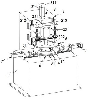
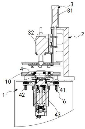
[0076] Such as Figures 2 to 10 As shown, a high-efficiency intelligent grinding processing center includes a processing table 1 and an installation column 2, and the installation column 2 is adjacent to the processing table 1, and also includes:
[0077] A hydraulic mechanism 3, the hydraulic mechanism 3 is installed on the top of the installation column 2, the hydraulic mechanism 3 is located directly above the processing table 1, and the hydraulic mechanism 3 includes a lifting assembly 31 and a compression adsorption assembly 32, so The lifting assembly 31 drives the compression adsorption assembly 32 to descend, and the compression adsorption assembly 32 is used to compress and position the annular workpiece 10 to be polished on the processing table 1;
[0078] A loading mechanism 4, the loading mechanism 4 is installed on the processing table 1, the loading mechanism 4 includes a loading tray 41 and a centering assembly 42, and the loading tray 41 is used to carry the an...
Embodiment approach
[0113] Such as Figure 11 As shown, as a preferred embodiment, the side grinding mechanism 7 includes:
[0114] A side sliding seat 71, the side sliding seat 71 is installed on the processing table 1 through a slide rail group 72, and the slide rail group 72 is arranged towards the loading mechanism 4;
[0115] A side grinding blade 73, the side grinding blade 73 is mounted on the side sliding seat 71, and the side grinding blade 73 is bonded and ground to the side wall of the annular workpiece 10; and
[0116] The side thrust cylinder 74 is installed on the processing table 1 , and the side thrust cylinder 74 pushes the side sliding seat 71 to be slidably arranged.
[0117] It should be noted that, in the process of grinding the upper and lower end faces of the annular workpiece 10 , the sidewall of the annular workpiece 10 is simultaneously ground by the side grinding blade 73 .
PUM
 Abstract
Description
Claims
Application Information
 - R&D
- Intellectual Property
- Life Sciences
- Materials
- Tech Scout
- Unparalleled Data Quality
- Higher Quality Content
- 60% Fewer Hallucinations
Browse by: Latest US Patents, China's latest patents, Technical Efficacy Thesaurus, Application Domain, Technology Topic, Popular Technical Reports.
© 2025 PatSnap. All rights reserved.Legal|Privacy policy|Modern Slavery Act Transparency Statement|Sitemap|About US| Contact US: help@patsnap.com


