Customized sponge packing material contour forming equipment
A molding equipment and contouring technology, which is applied in the field of custom sponge packaging contouring molding equipment, can solve problems such as low efficiency, irregular contours, time-consuming and labor-intensive problems, and achieve the effect of avoiding equipment damage and high work efficiency
- Summary
- Abstract
- Description
- Claims
- Application Information
AI Technical Summary
Problems solved by technology
Method used
Image

Examples
Embodiment 1
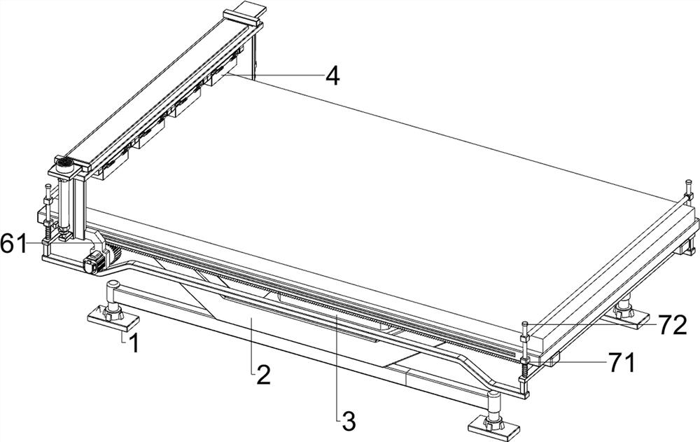
[0076] A custom sponge packaging material contour forming equipment, such as Figure 1-Figure 8 As shown, it includes a base 1, a workbench 2, a contour mold 4, a cutting mechanism 5 and a translation mechanism 6. The left and right sides of the bottom of the workbench 2 are symmetrically provided with a base 1, and the left side of the workbench 2 is provided with a cutting mechanism 5. Four contour molds 4 are arranged on the cutting mechanism 5 , and a translation mechanism 6 is arranged on the front side of the workbench 2 .
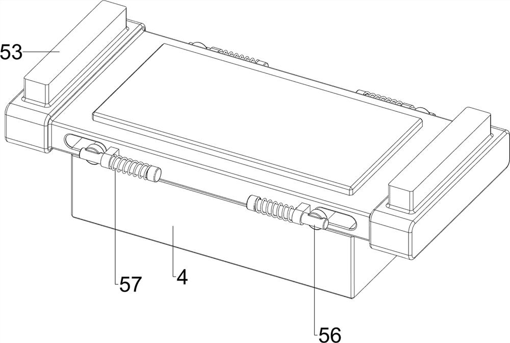
[0077] The cutting mechanism 5 includes a first sliding frame 51, an electric push rod 52, a second sliding frame 53, a buzzer 54, a heating plate 55, a clamping rod 56, a first spring 57 and a distance sensor 58. The first sliding frame 51 is provided in the upper left part of the sliding frame, and the electric push rod 52 is provided on the outside of the first sliding frame 51. The sliding type between the first sliding frame 51 top is provided w...
Embodiment 2
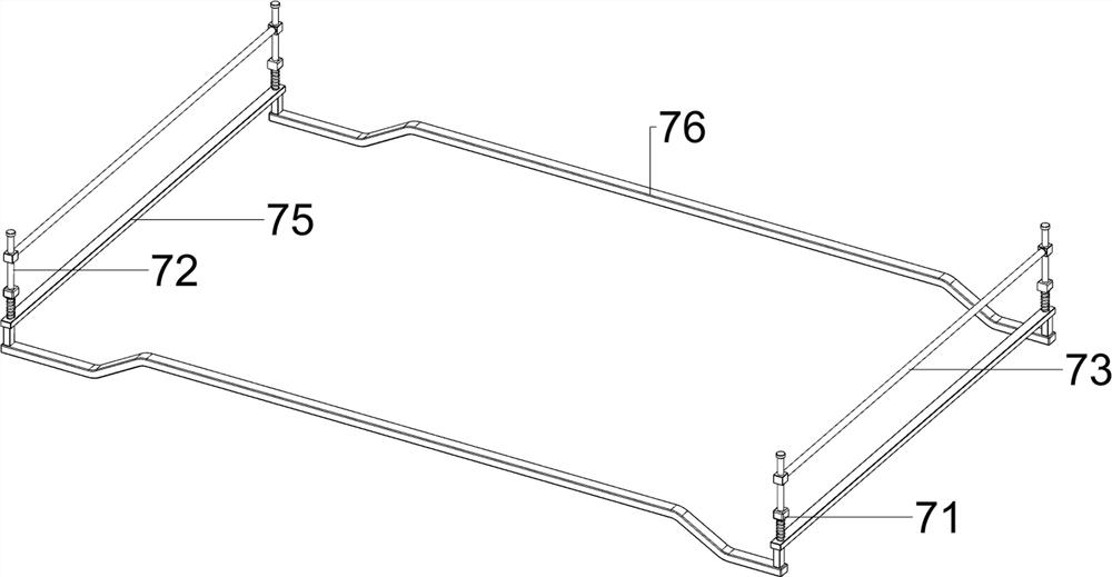
[0081] On the basis of Example 1, such as figure 1 , Figure 9 , Figure 10 , Figure 11 , Figure 12 , Figure 13 , Figure 14 , Figure 15 , Figure 16 and Figure 17 As shown, a clamping mechanism 7 is also included, and the clamping mechanism 7 includes a first guide sleeve 71, a sliding rod 72, a pressing rod 73, a second spring 74, a connecting rod 75 and a limit rod 76. The first guide bushing 71 is arranged symmetrically on the upper part of the side, and the middle part of the first guide bushing 71 is provided with a sliding rod 72, and the upper part of the two sliding rods 72 on the same side in the longitudinal direction is provided with a pressing rod 73. A connecting rod 75 is provided between the bottoms of the two sliding rods 72, a second spring 74 is provided between the connecting rod 75 and the two first guide sleeves 71 on the same side, and a limiting spring is arranged symmetrically between the bottoms of the connecting rods 75. The position ba...
PUM
 Abstract
Description
Claims
Application Information