
Drain board with high pressure resistance

A kind of technology of drainage board and board body

Inactive Publication Date: 2021-10-15
界首市通达塑业有限公司
View PDF1 Cites 0 Cited by
  • Summary
  • Abstract
  • Description
  • Claims
  • Application Information

AI Technical Summary

Problems solved by technology

[0004] The existing high-compression-resistant drainage boards have certain disadvantages in the process of use. The traditional drainage board adopts an integrally formed structure design, so that the bottom of the drainage board only has a few sets of raised support structures, thereby reducing the cost of the drainage board. The structural strength of the drainage board makes the local part of the drainage board prone to depression; secondly, the traditional drainage board does not have multiple splicing structures, which reduces the flexibility of the installation and use of the drainage board, making it unable to apply to different installation environments; at the same time, the traditional high pressure resistance The drainage board does not have a split installation structure. When the high-compression drainage board has local depressions, the user needs to replace the entire high-compression drainage board, and the high-compression drainage board is added. The maintenance cost will bring certain adverse effects to users

Method used


Image

  • Drain board with high pressure resistance
  • Drain board with high pressure resistance
  • Drain board with high pressure resistance

Examples


Embodiment 1

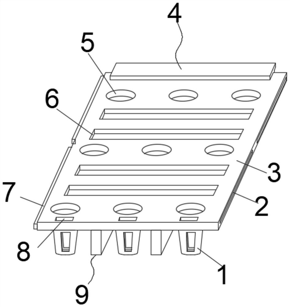
[0035] The outer surface of the upper end of the plate body 3 is provided with three groups of circular notches 5, and the outer surface of the upper end of the plate body 3 is located between the two groups of circular notches 5 and is provided with a bar-shaped notch 6. The setting of the shaped notch 6 makes the water body pass through the plate body 3, thereby being discharged from the bottom of the plate body 3, and the drainage operation is completed.

[0036] Support frame 9 comprises two groups of first clamping plates 18 and two groups of second clamping plates 19, and is fixed by thermoplastic welding between two groups of first clamping plates 18 and two groups of second clamping plates 19, and the cross section of support frame 9 is The well-shaped structure, utilizing the setting of the support frame 9, can support and fix the bottom of the support seat 1 when the support seat 1 is installed, thereby improving the structural strength of the support seat 1 and incre...

Embodiment 2

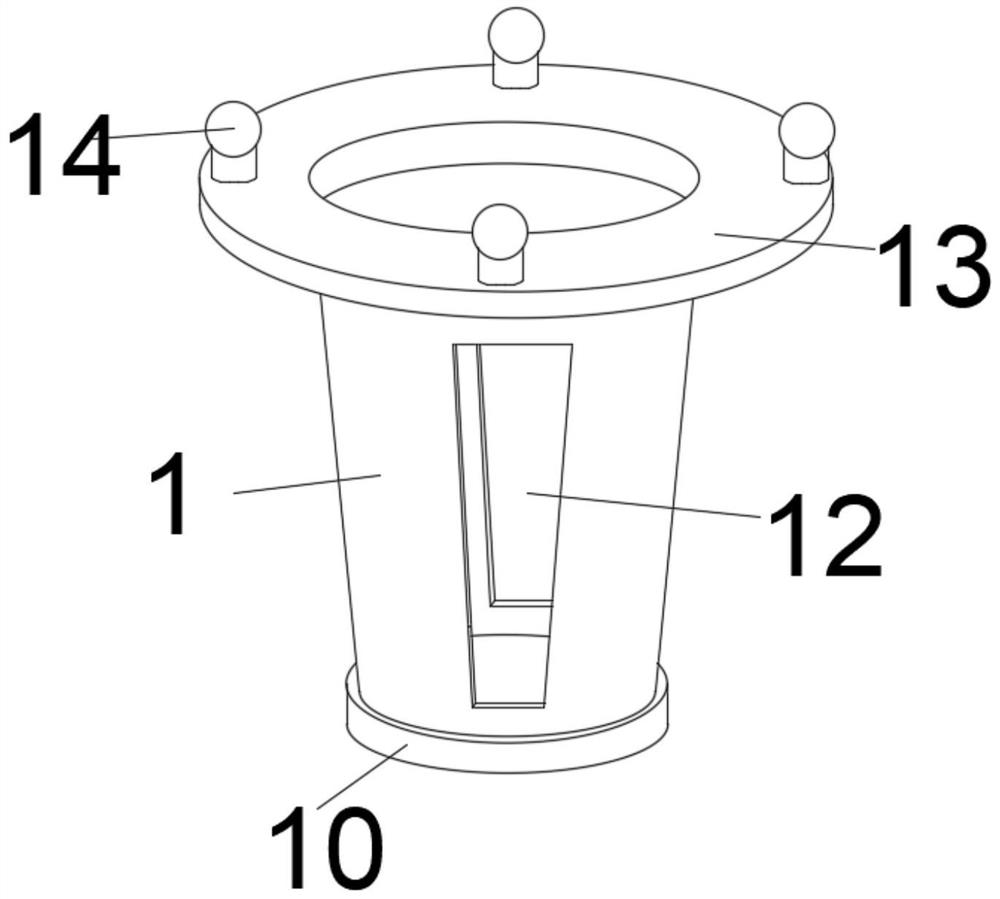
[0040] Two groups of drainage grooves 12 are provided through the side outer surface of the support seat 1, and the two groups of drainage grooves 12 are arranged side by side. Four groups of docking plugs 14 are installed on the upper part of the fixing ring 13, and the fixing ring 13 cooperates with the docking plugs 14 to support The installation of the seat 1 plays the role of splicing and fixing, and at the same time, the setting of the drainage groove 12 is used to make the support seat 1 have a side drainage structure.

[0041] Two sets of splicing grooves 2 are provided on the inner side of one end of the plate body 3, and two sets of splicing clips 7 are fixedly installed on the other end of the plate body 3. By using the setting of the splicing grooves 2 and the splicing clips 7, it is possible to facilitate the connection between the two groups of plate bodies 3. Splicing and fixing between.

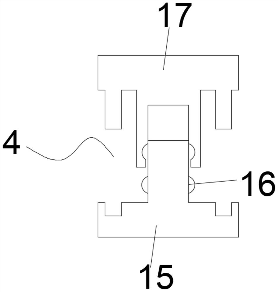
[0042] The combination clip 4 comprises an upper clip 17 and a lower clip...


PUM


Abstract

The invention discloses a drain board with high pressure resistance. The drain board comprises a supporting seat and a board body, wherein the supporting seat is installed at the bottom of the board body in a spliced mode, a supporting frame is installed on the side, close to the supporting seat, of the outer surface of the bottom of the board body in a spliced mode, a combined clamping strip is installed on the outer surface of one end of the board body in a spliced mode, and fixing inserting grooves which are matched with the combined clamping strips are formed in the inner sides of both ends of the board body. Force can be uniformly dispersed by the supporting frame of the #-shaped structure, so that pressure is prevented from being concentrated in one position of the board body; additionally, when the board body is drained, water can be discharged to the lower part of the board body through round notches and strip-shaped notches in the board body; additionally, drainage grooves of a first clamping plate and a second clamping plate are matched, so that the water is discharged; and the supporting frame is arranged, so that the reinforcing and supporting effects on the board body and the supporting seat can be achieved, the drain board with high pressure resistance has a pressure resistant reinforcing structure, and the overall structural strength of the drain board is increased.

Description

technical field [0001] The invention belongs to the technical field of drainage boards, in particular to a drainage board with high compression resistance. Background technique [0002] The traditional drainage method uses masonry and tiles as the filter layer, and uses more pebbles as the drainage layer or gravel as the filter layer to drain the water to the designated place, and uses drainage boards instead of the pebble filter layer to drain water. Time, labor and energy saving, but also reduce the load of the building. [0003] The patent document of patent No. CN213625902U discloses a two-way composite drainage board, which includes: the main body of the drainage board, strip-shaped protrusions, reinforcement blocks, drainage grooves and slots. Pressure plate, the anti-compression plate is a corrugated structure, an elastic pad is arranged between the internal cavity of the main body of the drainage plate and the anti-pressure plate, and an anti-corrosion layer is inst...

Claims


Application Information

Patent Timeline
Patent Type & Authority Applications(China)
IPC IPC(8): E02D3/10
CPCE02D3/10
Inventor 朱峰朱楠楠
Owner 界首市通达塑业有限公司
Features
  • Generate Ideas
  • Intellectual Property
  • Life Sciences
  • Materials
  • Tech Scout
  • Unparalleled Data Quality
  • Higher Quality Content
  • 60% Fewer Hallucinations
Learn More