Method of controlling an industrial system, control system and industrial system

A technology for industrial systems, control systems, applied in general control systems, control/regulation systems, manufacturing tools, etc., to solve problems such as damage, robot program failure, material temperature fluctuations, etc.

Pending Publication Date: 2021-10-15
ABB (SCHWEIZ) AG
1 Cites 0 Cited by

AI-Extracted Technical Summary

Problems solved by technology

[0005] Robot programs can fail for various reasons, such as due to damage to robot fingers or grippers, gearbox oil leaks, and temperature fluctuations in the environment th...

Method used

[0058] By collecting data on the results of actions, such as execution time, probability of success, and de...

Abstract

A method of controlling an industrial system (10) comprising at least one agent (14, 16), the method comprising providing a representation of the industrial system (10) as a finite state machine (36), the state machine (36) comprising a plurality of nodes (38) and a plurality of edges (40), where each node (38) represents a discrete system state of the industrial system (10), each edge (40) represents an action for a state transition between system states represented by two of the nodes (38), and at least one execution value (42) is associated with at least one of the edges (40); executing at least one action by the at least one agent (14, 16), the at least one action being represented by at least one of the edges (40); and modifying at least one execution value (42) associated with at least one of the edges (40) representing the at least one executed action, based on an outcome of the at least one executed action.

Application Domain

Programme controlProgramme-controlled manipulator

Technology Topic

Process engineeringManufacturing engineering +6

Image

  • Method of controlling an industrial system, control system and industrial system
  • Method of controlling an industrial system, control system and industrial system

Examples

  • Experimental program(1)

Example Embodiment

[0037] Hereinafter, a method of controlling an industrial system comprising at least one agent is used to control an industrial system including at least one agent, and an industrial system including a control system. The same reference numerals will be used to represent the same or similar structural features.
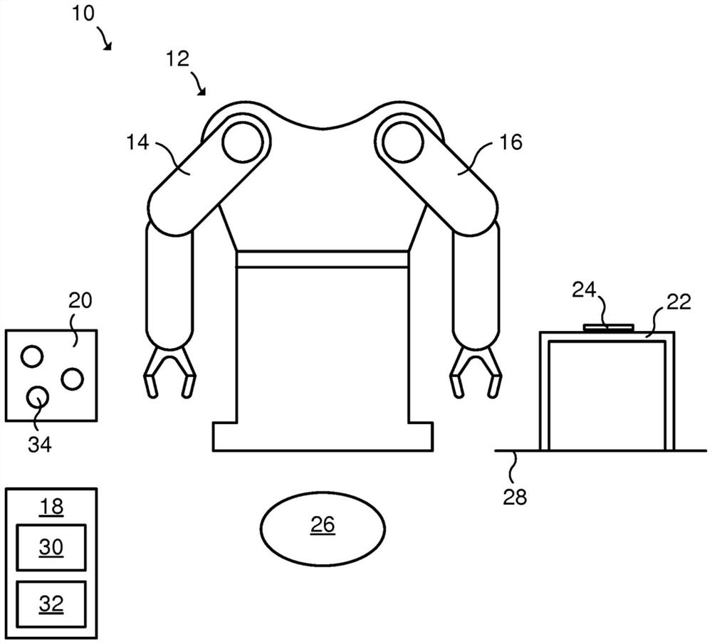
[0038] figure 1Schematically shows an illustrative example of an industrial system 10. Industrial system 10 of this example comprises an industrial robot having two arms 14, 16 of the manipulator 12. Industrial system 10 of this example further includes a control system 18, feeder 20, table 22, table supporting portion (Coaster) 24 and 22 on the hopper 26. Table 22 is positioned on the floor 28. Two arms 14, 16 of the robot 12 constituting a proxy agent having discrete states. Therefore, the industrial system 10 includes a left arm 14 in the form of a first agent and the second agent 16 in the form of right arm. However, the industrial system 10 may include alternative or additional types of agents, for example a conveyor belt, a mobile robot, or other physical actuators.
[0039] The control system 18 includes a data processing device 30 (e.g., a central processing unit, CPU) and a memory 32. The computer program is stored in the memory 32. A computer program comprising program code which when executed by a data processing device 30, the program code causes the data processing device 30 performs any of the steps performed in accordance with the present disclosure according to the present disclosure in any steps or order.
[0040] Industrial System 10 is configured to perform the following tasks or actions. Left arm 1420 is picked up from the feeder 34 and the article 34 to the article 16 of the right arm, the right arm 16 allows the right arm 16 to receive an item 34. Item 16 receives the right arm 34. The supporting portion 24 of the right arm 16 is placed in the article 34. Thus, the right arm the left arm 14 of each arm 16 and having a state represented by a discrete number Agent 0 "empty" and dispersion agent represented by the digital 1 state "possession." Left arm 14 and right arm 16 can also have additional agents state, but for purposes of this example is not necessary to consider them. Suppose industrial systems 10 permits identification of agents considered the state of each sensor, such that at each time point all agents are known in the state of the agent.
[0041] figure 2 Schematically represents figure 1 The industrial system 10 is represented as a finite state machine 36. System status may be expressed as a combination of the state of all the agents of the industrial system 10. The state machine 36 includes an industrial system model 10.
[0042] like figure 2 Shown, comprises a plurality of nodes represents the state machine 38 and a plurality of edge 40. Each node 38 represents a discrete system state 10 of an industrial system. Each edge 40 is connected between two nodes 38, and indicates the state between the two nodes represented by the two systems 38 converts the desired operation state.
[0043] Each node 38 comprises means for each agent, each component value corresponding to a respective proxy agent status. Thus, due to previous assumptions, all agents state at each time point is known, the state of the system is always known.
[0044] exist figure 1 with figure 2 In the example, each node 38 has two components. The first state indicates that the agent left arm member 14 and second member 16 of the right arm represents the state of the agent. The first member and the second member may be respectively 0 and 1 values ​​( "empty" and "possession"). Industrial systems 10 may be employed whereby four unique system state (0,0), (0,1), (1,0) and (1,1).
[0045] To convert between different system states, one of 14, 16 or both agents needed to carry out. Available actions depend on the industrial system configuration 10. In the present example, the left arm 14 is configured to perform the "pick up" from the "P" represents a "transfer" and by the "TL" represents "left throw" operation by the "H" represents the right arm 16 is configured for the implementation of "place" and "right throw" operation by the "TR" indicates "received" by the "S" represented by "R" denotes a.
[0046] Programmers define multiple rules 10 to perform a task familiar with the industry and become familiar with the system configuration by the industrial system 10. Rules to determine proper operation under certain preconditions to be taken in order to achieve the desired post-condition. Each rule to be changed includes at least one agent status preconditions, postconditions states, and at least one agent at least one agent causes a corresponding state conversion action. For example, a rule may be determined each time the article holder 14 of the left arm 34, the appropriate action is to "transfer" H and agent status after the operation is expected left arm 14 is "empty" 0. Further rules can determine the state of the left arm 14 agents should not be in the absence of interaction with the right arm 16 from the "possession" 1 to "empty" 0. The rules may further determine the status of the agent is not in the right arm 16 and the case 14 without interaction from the left arm "empty" 0 becomes "possession" 1.
[0047] Industrial hardware configuration will allow the agent 10 of the left arm 14 from the state of "possession" 1 to "empty" 0 without interworking with the right arm 16, namely "left throw" TL by performing the operation. However, the rules reflect a given task to be performed by the industrial system 10 are not allowed to do so because the 34 items into the trash 26 will not contribute to the aim to perform a given task.
[0048] When the rule is set, the potential state transition between different system states may be defined. Nodes are connected to the edge 40 by means 38 therebetween. One node of each pair 38 as a pre-condition of the node 38 to another node 38 in each pair 38 as nodes and postconditions. Each represents at least one edge 40 by the operation of a direct conversion between the two state 38 represents the state of the system nodes.
[0049] In this example, not all of the nodes 38 by means of the edge 40 can be directly connected. Operation may be employed but potentially available status does not meet the rule conversion example shown by dashed arrows. For example, while the industrial system 10 can perform conversion from the system state (1,0) to (0,0) state directly, i.e., by the operation of "left throw" TL, this conversion rule is not satisfied.
[0050] It should be noted, has four nodes comprising a very simple state machine 38 of the industrial system represented by 10, 40 and the total number of edges connected to the potential becomes relatively high. For a more comprehensive industrial system 10, it is not easy to detect hand side 40. In contrast, 38, edge 40 may be automatically detected by evaluating the plurality of nodes, taking into account the rules, regardless of whether or not by means of the edge 40 are directly connected. Then available may be optimized by determining the edge list 40 is preferably a state transition chain. Evaluation and optimization of this type are previously known, for example from the international patent application WO 2018086677A1 known.
[0051] The state machine 36 of the present disclosure further comprises a plurality of execution value assigned to the 42 edge 40, as described below. 42 may be allocated to one execution value, a plurality or all of the edges 40. figure 2 Agent shows a state (0,1), and an example of edge 40 associated with the implementation of values ​​between (0,0) 42.
[0052] Once the state machine has been provided representation, including a plurality of programs for controlling the operation of the industrial system based on the state machine 10 is provided representation. The program may include a sequence of various actions, such as a mobile proxy 14,16. The program then runs multiple times, the agent 14, 16 such that the corresponding action is performed.
[0053] Suppose during program execution right arm 16 may not be an article 34 is placed on the supporting portion 24. When the article 34 could not be placed on supporting portion 24, the article 34 may fall next table 24 the supporting portion 22, or upon the floor 28. During program execution, the results of the operation are recorded.
[0054] In this example, the value of the proxy execution state (0,1) operation between (0,0) comprises a discrete probability distribution 42 and x, y, z, where x indicates success placing the article on the supporting portion 24 of the 34 results probability, Y represents a failure to articles 34 is placed on the supporting portion 24, wherein the probability of the article 34 retained in the result table 22, and z represents 34 failed the article 24 is placed on the supporting portion, wherein the results of probability on the floor 28 items 34 fell. Thus, the success of state transition probability proxy execution value (0,1) operation between (0,0) and 42 showing the operation of "x", the operation fails and transition probability "article 34 on the table 22 in the end result y "the results and the operation fails and the article 34 on the floor 28 of the end of the transition probability" Z. " Thus, for each execution of the action, the action was successful or what the results were recorded. In this example, each of the probability distributions may be referred performed and these values ​​constitute execution value may also be referred to as execution data.
[0055] By considering the transition probability, the state machine represents a more realistic, it can track a high level of performance of each agent 14, 16, and to avoid undesirable system status. For example, if you do not want the article 34 falls on the floor 28, it may be avoided with a certain probability associated execution value indicating article 34 falls on the floor 42 of the 28 operation. Accordingly, the program can be made less prone to errors and can reduce the failure rate of 10 industrial systems.
[0056] However, the distribution of x, y, z is merely one example of the disclosure of the present execution value of 42. Alternatively or additionally, execution value of type 42 can be recorded and assigned to the associated edge 40, for example, the execution time for each action. For example, in the case 36 includes a state machine 42 performs an operation value indicating a time of execution, an improved time of the program optimization may be performed. 42 indicates execution value value selecting operation.
[0057] Program may be run at the same time record the results of each action many times, for example, the probability that the result of the execution time and success. The state machine 10 of the industrial system representation by modifying the execution value is updated based on the actual results represented by the respective sides 40 of the edge 40 performs the operation of 42. The updated more frequently or less frequently occurring, for example after the operation or after the completion of each cycle comprising a plurality of completed actions.
[0058] By collecting data on the operation result, such as the execution time, and the degree of success probability of success, it can improve the execution quality for industrial process control system 10.
[0059] Member 36 thus based state machine that can cause a different operation state of the system is modified and in what probability. By means of a state machine 36 performs the modified values ​​of 42 can more accurately determine the frequency of an operation failure, the manner in which the operation fails, and how long the execution time of the operation.
[0060] Has been performed based on the modified values ​​42, various types of optimization routines may be executed, the execution value modified based on the results of operation executed, the executing operation cycle time is minimized e.g., to minimize errors, improve efficiency, minimize waste and / or minimize power consumption. Markov decision process (MDP) modified the state machine 36 may be used to create, for example, updating. Thus, the entire industrial system high-level program 10 may be modeled as MDP and efficiently solved through good initialization. For example, MDP Bellman update can be used, such as value iteration, Q learning and policy iteration to solve. Then, based on the implementation of the modified value 42, the state machine 36 state transition can be optimized.
[0061] Further, execution value 42 may be used to improve the tracking error provider. To this end, a first plurality of values ​​42 may be determined based on the performed action performed. Then the first actuator 42 and the second value associated execution value 42 is compared. Performing a second state value 42 may be executed, for example, a value of 42 or 36 is performing other reference value 42. Then a set of values ​​42 may be performed first to extract the value of a set of 42 different from the first execution of the second execution value of its associated 42.
[0062] In this regard, for example, to assess whether the overall set of difference values ​​42 performs the first execution of the second execution value 42 associated with the steady state change is greater than 42. Alternatively, a probability distribution can be used to assess a second set of first execution value 42 42 whether the overall execution value different from the corresponding. As a further example, the second execution history value from an associated probability distribution 42 of the first report execution probability value 42 may be calculated.
[0063]If it is determined that the overall probability distribution of the first execution value 42 indicates an incompetent event, there is an error. Further, if the first execution value 42 in these groups is all or substantially all belongs to the edge 40 associated with the operation performed by the specific proxy 14, 16, it can be concluded that there is an error in the agent 14, 16. In this way, early detection can be reduced by the performance of the agent 14, 16. The warning can then be issued to the operator.
[0064] Therefore, instead of all potential error sources of direct monitoring industrial system 10 (this may require thousands of sensors), but monitor the actual performance of the industrial system 10, and can derive the conclusion of errors or other changes based on the actual performance of the industrial system 10. . Since all the actions of the industrial system 10 are executed by one or more agents 14, 16, the failure of one agent 14, 16 is likely to be related to several operations involving the same agents 14, 16.
[0065] If only one determined first execution value 42 is considered, it may be difficult to determine whether the difference between the determined first execution value 42 and the corresponding second execution value 42 of the state machine 36 is caused by an error, or if difference In the range of standard deviations or steady state changes. By considering the determined first execution value 42, a relatively high deviation is required to have sufficient confidence to define an error. However, by co-evaluating a plurality of determined first execution values ​​42 in accordance with the corresponding second execution value 42 (or according to the target execution value 42), the error exists in the agent 14, 16, even at the same agent 14 There is only relatively small deviations in multiple determining values ​​42 of 16.
[0066] Although the present disclosure has been described with reference to an exemplary embodiment, it should be understood that the invention is not limited to the contents already described above. For example, it will be appreciated that the size of the component can vary depending on the needs.

PUM

no PUM

Description & Claims & Application Information

We can also present the details of the Description, Claims and Application information to help users get a comprehensive understanding of the technical details of the patent, such as background art, summary of invention, brief description of drawings, description of embodiments, and other original content. On the other hand, users can also determine the specific scope of protection of the technology through the list of claims; as well as understand the changes in the life cycle of the technology with the presentation of the patent timeline. Login to view more.
Why Eureka
Try Eureka