Rapid catalyst coating device suitable for ceramic filter tube

A catalyst device and catalyst technology, which is applied to the device and coating of the surface coating liquid, can solve the problems of affecting production efficiency, affecting the use effect of ceramic filter tubes, and uneven catalyst coating, so as to achieve the goal of improving production efficiency Effect

Pending Publication Date: 2021-10-19
安徽紫朔环境工程技术有限公司
View PDF12 Cites 1 Cited by
  • Summary
  • Abstract
  • Description
  • Claims
  • Application Information

AI Technical Summary

Problems solved by technology

Ceramic filter tubes are mainly used for denitrification and dust removal of industrial flue gas. The interior is an intricate porous structure, which has the characteristics of high denitrification efficiency and strong dust removal ability. , but in the prior art, when the ceramic filter tube is coated with catalyst, the ceramic filter tube is directly immersed in the catalyst, and then taken out directly, which

Method used


Image

  • Rapid catalyst coating device suitable for ceramic filter tube
  • Rapid catalyst coating device suitable for ceramic filter tube
  • Rapid catalyst coating device suitable for ceramic filter tube

Examples


Embodiment 1

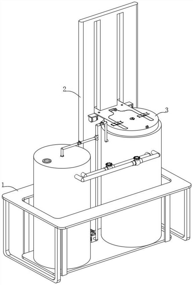
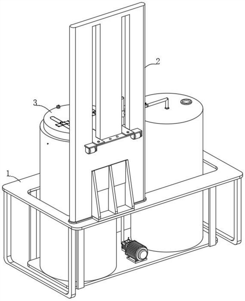
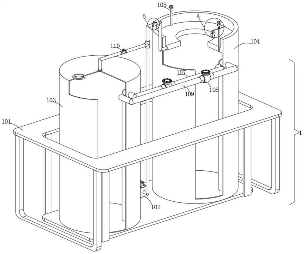
[0031] Embodiment one, with reference to Figure 1-9: A kind of rapid coating catalyst device applicable to ceramic filter tubes, comprising: a storage mechanism 1, the storage mechanism 1 includes a bottom frame 101 and conveying parts, the setting of the bottom frame 101 provides an installation basis for other functional parts of the equipment, the bottom The inner bottom surface of the frame 101 is fixedly connected with a catalyst stock solution barrel 103 near the center of one side edge. The catalyst stock solution barrel 103 is set up to facilitate the effective storage of the catalyst. The inner bottom surface of the bottom frame 101 is fixedly connected with a vacuum suction pump on one side of the catalyst stock solution barrel 103 102. The vacuum pump 102 is set up to provide the power required for catalyst transportation. The structure and principle of the vacuum pump 102 belong to the prior art, and will not be described in detail here. Its model can be selected a...


PUM


Abstract

The invention discloses a rapid catalyst coating device suitable for a ceramic filter tube. The rapid catalyst coating device comprises a storage mechanism, the storage mechanism comprises a bottom frame and a conveying part, a catalyst stock solution barrel is fixedly connected to the position, close to the center of the edge of one side, of the inner bottom face of the bottom frame, a vacuum suction pump is fixedly connected to the position, located on one side of the catalyst stock solution barrel, of the inner bottom face of the bottom frame, a vacuum chamber is fixedly connected to the position, close to the center of the other edge, of the inner bottom surface of the bottom frame, a liquid level detector body is fixedly connected to the position, close to the center, of the inner top surface of the vacuum chamber, and the conveying part is arranged on the catalyst stock solution barrel and the vacuum chamber. According to the rapid catalyst coating device, when a ceramic filter pipe body is effectively placed in the vacuum chamber, a control valve on a second connecting pipe is closed, so that a vacuum suction pump can effectively pump out internal air through vacuum, and a catalyst in a catalyst raw material barrel can be effectively injected into the vacuum chamber through a first conveying pipe under the limitation of a one-way valve.

Description

technical field [0001] The invention belongs to the technical field of filter tubes, in particular to a rapid coating catalyst device suitable for ceramic filter tubes. Background technique [0002] In recent years, with the improvement of industrial flue gas emission requirements, new treatment technologies have also been continuously innovated, among which ceramic filter tube technology has gradually become a key development direction in the field of flue gas denitrification and dust removal. Ceramic filter tubes are mainly used for denitrification and dust removal of industrial flue gas. The interior is an intricate porous structure, which has the characteristics of high denitrification efficiency and strong dust removal ability. , but in the prior art, when the ceramic filter tube is coated with catalyst, the ceramic filter tube is directly immersed in the catalyst, and then taken out directly, which leads to the excess catalyst adhering to the surface of the directly ta...

Claims


Application Information

Patent Timeline
IPC IPC(8): B05C3/109B05C13/02B05C11/10B05C15/00
CPCB05C3/109B05C13/02B05C11/101B05C15/00
Inventor 项泽顺王洪明徐淮北张矿孟祥民
Owner 安徽紫朔环境工程技术有限公司
Why Eureka
Try Eureka