
Ball floating valve device and water tank device

A float valve and water tank technology, applied in the direction of valve device, valve operation/release device, valve details, etc., can solve the problems of port fouling, increased port blockage, difficulty in obtaining precise control of water inflow, etc., to achieve the possibility Small, to avoid the effect of cleaning valve parts

Pending Publication Date: 2021-10-19
SUQIAN HANSHU ENVIRONMENTAL PROTECTION EQUIP CO LTD
View PDF0 Cites 0 Cited by
  • Summary
  • Abstract
  • Description
  • Claims
  • Application Information

AI Technical Summary

Problems solved by technology

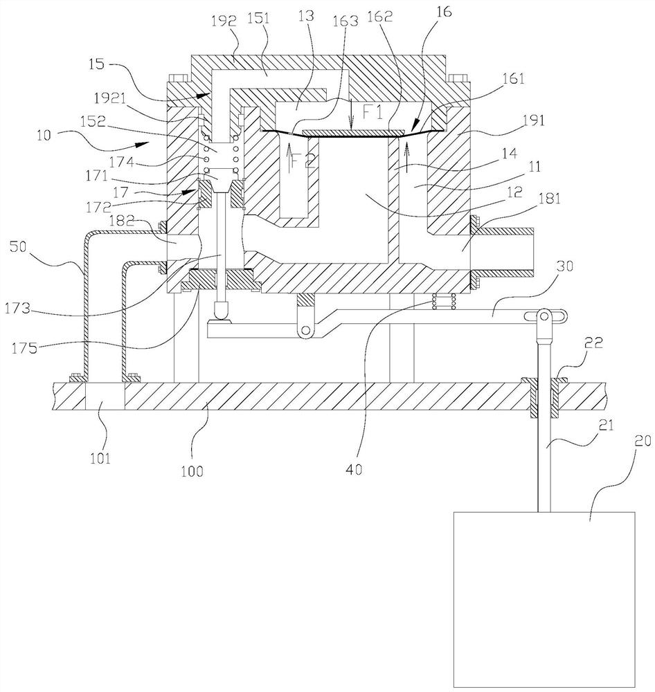
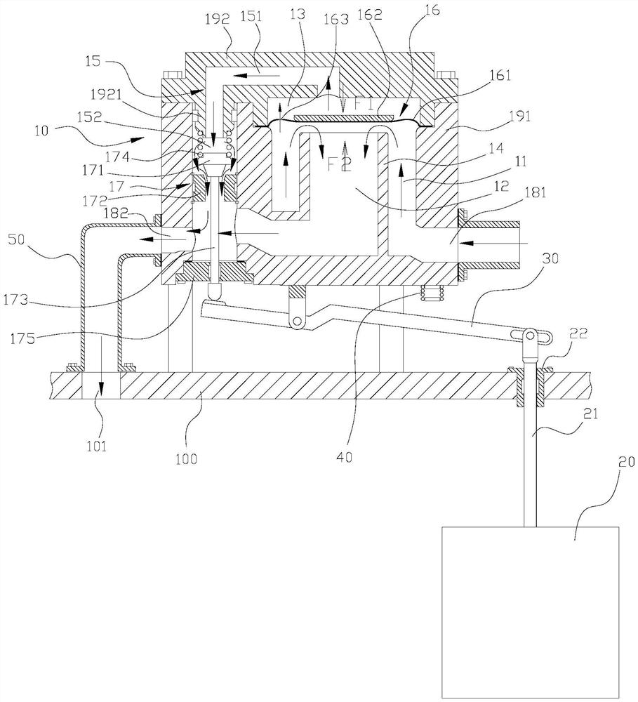
[0004] Although the above-mentioned float valve can control the water source to supply water to the water tank, however, because the float of the above-mentioned float valve directly controls the valve core through the rod component, this leads to the following defects: the amount of water entering is difficult to obtain precise control
[0007] The rod part makes the port of the control flow channel open, and part of the water of the water source will also flow out from the port, and this requires that the valve part as a whole needs to be assembled inside the water tank, which is bound to be unfavorable for cleaning the valve part
[0008] In addition, in order to reduce the flow of water flowing out from the port of the control flow channel, the port is usually set smaller, and because the port is located above the liquid level, it is easy to contact with air, which is easy to foul the port, thereby increasing the possibility of port blockage

Method used


Image

  • Ball floating valve device and water tank device
  • Ball floating valve device and water tank device

Examples


Embodiment Construction

[0056]In order to make the purpose, technical solutions and advantages of the embodiments of the present invention more clear, the technical solutions of the embodiments of the present invention will be clearly and completely described below in conjunction with the drawings of the embodiments of the present invention. Apparently, the described embodiments are some, not all, embodiments of the present invention. Based on the described embodiments of the present invention, all other embodiments obtained by persons of ordinary skill in the art without creative efforts shall fall within the protection scope of the present invention.

[0057] Unless otherwise defined, the technical terms or scientific terms used in the present invention shall have the usual meanings understood by those skilled in the art to which the present invention belongs. "First", "second" and similar words used in the present invention do not indicate any order, quantity or importance, but are only used to di...


PUM


Abstract

The invention discloses a ball floating valve device and a water tank device. The ball floating valve device comprises a valve part, a floater and a rod part, wherein the valve part comprises a water inlet, a water outlet, a first chamber communicating with the water inlet, a second chamber communicating with the water outlet, a first valve element mechanism used for controlling connection and disconnection of the first chamber and the second chamber, a third chamber directly or indirectly communicating with the water inlet to enable the first chamber is separated from the second chamber by applying pressure to the first valve element mechanism through pressure water guided from the water inlet, a control flow channel connected between the water outlet and the third chamber, and a second valve element mechanism used for controlling connection and disconnection of the control flow channel, wherein the floater drives the second valve element mechanism through the rod part so as to control connection and disconnection of the control flow channel.

Description

technical field [0001] The invention relates to the technical field of water purification, in particular to a float valve device and a water tank device. Background technique [0002] In the field of water purification technology, a float valve is usually used to control the liquid level of the water tank, so that the external water source can simultaneously supply water to the water tank while taking water from the water tank, so that a certain amount of water is always stored in the water tank. [0003] Float valves in the prior art generally include a float for sensing the liquid level in the water tank and a valve component for controlling water supply to the water tank; the valve component has a water inlet, a water outlet and a spool positioned between the water inlet and the water outlet, and the water inlet Connected to the water source; the float is linked with the spool in the valve part by a rod part (such as a connecting rod). The water port is connected, so tha...

Claims


Application Information

Patent Timeline
Patent Type & Authority Applications(China)
IPC IPC(8): F16K7/12F16K21/18F16K31/365F16K31/26
CPCF16K7/12F16K21/18F16K31/365F16K31/26
Inventor 刘果刘小菡
Owner SUQIAN HANSHU ENVIRONMENTAL PROTECTION EQUIP CO LTD
Learn More