
An energy-saving oil fume fan with automatic oil discharge function

An energy-saving, automatic exhaust technology, applied in the direction of oil fume removal, cleaning methods using tools, household appliances, etc., can solve the problems of reducing the oil fume suction performance of the impeller, increasing the energy consumption of the fume fan, increasing the weight of the impeller, etc., to achieve high efficiency and stability Work efficiency, improve power transmission efficiency, improve the effect of performance

Active Publication Date: 2022-04-12
湖南金诺动力设备制造有限公司
View PDF13 Cites 0 Cited by
  • Summary
  • Abstract
  • Description
  • Claims
  • Application Information

AI Technical Summary

Problems solved by technology

[0002] The motor of the existing range fume blower is usually arranged outside the case, so that the output shaft of the motor and the rotating shaft of the impeller need to be connected through transmission components, thereby reducing the transmission efficiency, resulting in increased energy consumption of the range fume fan, and the fume After the fan has been working for a period of time, thicker oil stains will adhere to the blades and the inner wall of the bellows. On the one hand, it needs to be cleaned regularly, which is time-consuming and labor-intensive. Since the accumulation of oil stains increases the weight of the impeller, which in turn increases the output of energy consumption and reduces the performance of the impeller to absorb oil fume, in view of this, we propose an energy-saving oil fume fan with automatic oil discharge function

Method used


Image

  • An energy-saving oil fume fan with automatic oil discharge function
  • An energy-saving oil fume fan with automatic oil discharge function
  • An energy-saving oil fume fan with automatic oil discharge function

Examples


Embodiment Construction

[0030] The following will clearly and completely describe the technical solutions in the embodiments of the present invention with reference to the accompanying drawings in the embodiments of the present invention. Obviously, the described embodiments are only some, not all, embodiments of the present invention. Based on the embodiments of the present invention, all other embodiments obtained by persons of ordinary skill in the art without creative efforts fall within the protection scope of the present invention.

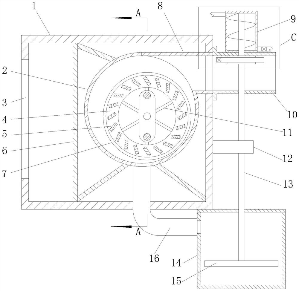
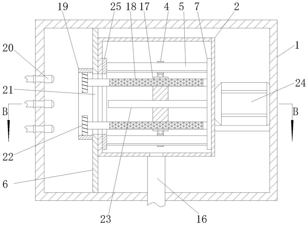
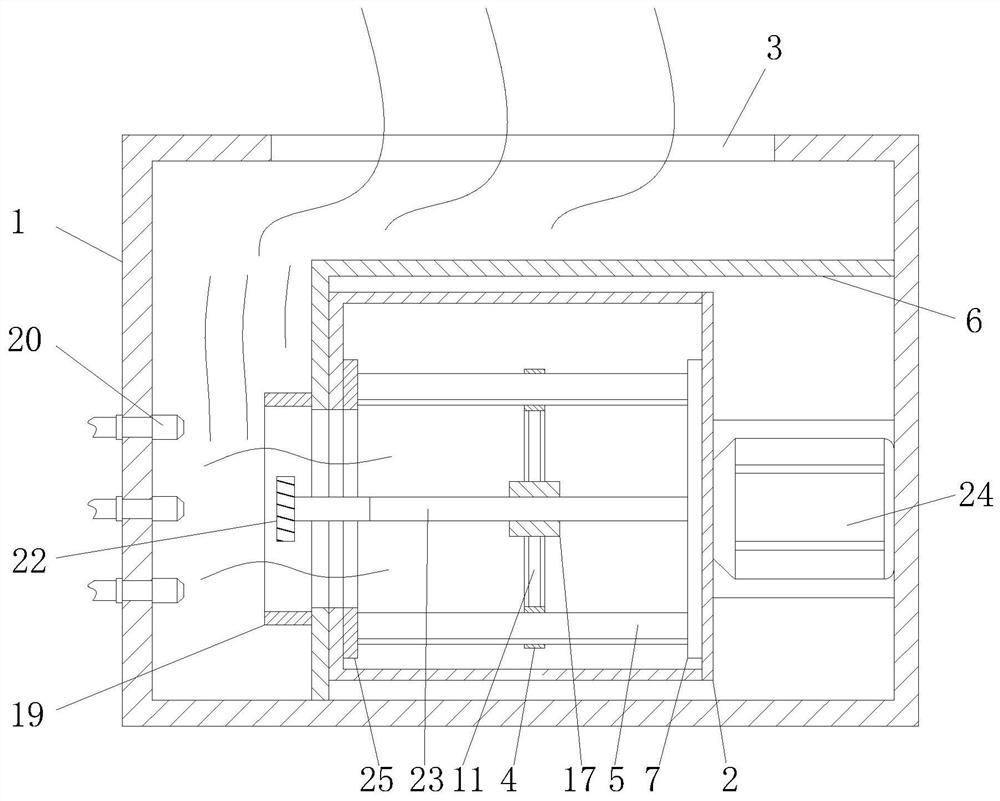
[0031] see Figure 1 to Figure 7 , the present invention provides a technical solution: an energy-saving oil fume blower with automatic oil discharge function, including a chassis 1, and also includes:

[0032] The bellows 2 is arranged in the cabinet 1, and the bellows 2 is provided with an impeller, and the impeller is connected to the output shaft of the motor 24 through transmission;

[0033] Oil scraping mechanism, the oil scraping mechanism is connected to t...


PUM


Abstract

The invention relates to the field of range hoods, in particular to an energy-saving range hood fan with an automatic oil discharge function, which includes a chassis, and also includes: a bellows arranged in the chassis, and an impeller is arranged in the bellows, and the impeller and the output shaft of the motor are driven Connection; oil scraping mechanism, the oil scraping mechanism is connected with the impeller drive, and the oil scraping mechanism is used to scrape off the oil stains adhered to the surface of the impeller in real time; the cleaning mechanism, the cleaning mechanism is used to clean the surface of the impeller and the inner wall of the bellows, and clean The mechanism is driven by the wind discharged by the impeller; the sewage discharge mechanism is used to discharge and collect the oil accumulated in the bellows, and the sewage discharge mechanism is connected with the bellows, and the sewage discharge mechanism is electrically connected with the cleaning mechanism. This energy-saving oil fume fan with automatic oil discharge function improves power transmission efficiency, helps reduce energy consumption, improves the performance of the impeller, and then improves the oil fume exhaust capability, and can automatically discharge and collect oil pollution without manual cleaning, reducing Difficulty of operation.

Description

technical field [0001] The invention relates to the field of range hoods, in particular to an energy-saving range hood fan with an automatic oil discharge function. Background technique [0002] The motor of the existing range fume blower is usually arranged outside the case, so that the output shaft of the motor and the rotating shaft of the impeller need to be connected through transmission components, thereby reducing the transmission efficiency, resulting in increased energy consumption of the range fume fan, and the fume After the fan has been working for a period of time, thicker oil stains will adhere to the blades and the inner wall of the bellows. On the one hand, it needs to be cleaned regularly, which is time-consuming and labor-intensive. Since the accumulation of oil stains increases the weight of the impeller, which in turn increases the output of energy consumption and reduces the performance of the impeller to suck oil fume, in view of this, we propose an ene...

Claims


Application Information

Patent Timeline
Patent Type & Authority Patents(China)
IPC IPC(8): F24C15/20B08B1/04
CPCF24C15/2035F24C15/2057B08B1/32
Inventor 李维温碧艺梁锦波孙志波刘铮铮张孔万浩
Owner 湖南金诺动力设备制造有限公司
Learn More