
Oil smoke purifier purification efficiency detection device

A technology of oil fume purifier and purification efficiency, which is applied in the direction of measuring devices, machine/structural component testing, instruments, etc., which can solve the problems of low detection accuracy, uneven oil fume particles, and inability to apply oil fume purifier detection, etc., and achieve detection accuracy Guaranteed, high uniformity of oil mist delivery

Active Publication Date: 2021-10-19
张家港朗亿机电设备有限公司
View PDF14 Cites 0 Cited by
  • Summary
  • Abstract
  • Description
  • Claims
  • Application Information

AI Technical Summary

Problems solved by technology

[0002] At this stage, it is necessary to test the purification efficiency of lampblack in restaurants, canteens and other catering industries. At present, the detection work is carried out on site. For example, the patent number is: 202021955573.7, a device for testing the purification efficiency of household range hoods. A device for detecting the purification efficiency of oil fume is disclosed. The principle of the detection is to detect under the normal working environment of the equipment, but this detection method will make the oil fume particles in the sampling pipeline uneven, so the detection results are not accurate. , and the temperature of the oil will also affect the detection accuracy. At the same time, this detection cannot be applied to the detection of large quantities of oil fume purifiers. It is difficult to arrange the detection equipment and the detection accuracy is low. device

Method used


Image

  • Oil smoke purifier purification efficiency detection device
  • Oil smoke purifier purification efficiency detection device
  • Oil smoke purifier purification efficiency detection device

Examples


Embodiment Construction

[0037] The present invention will be described in further detail below through specific examples.

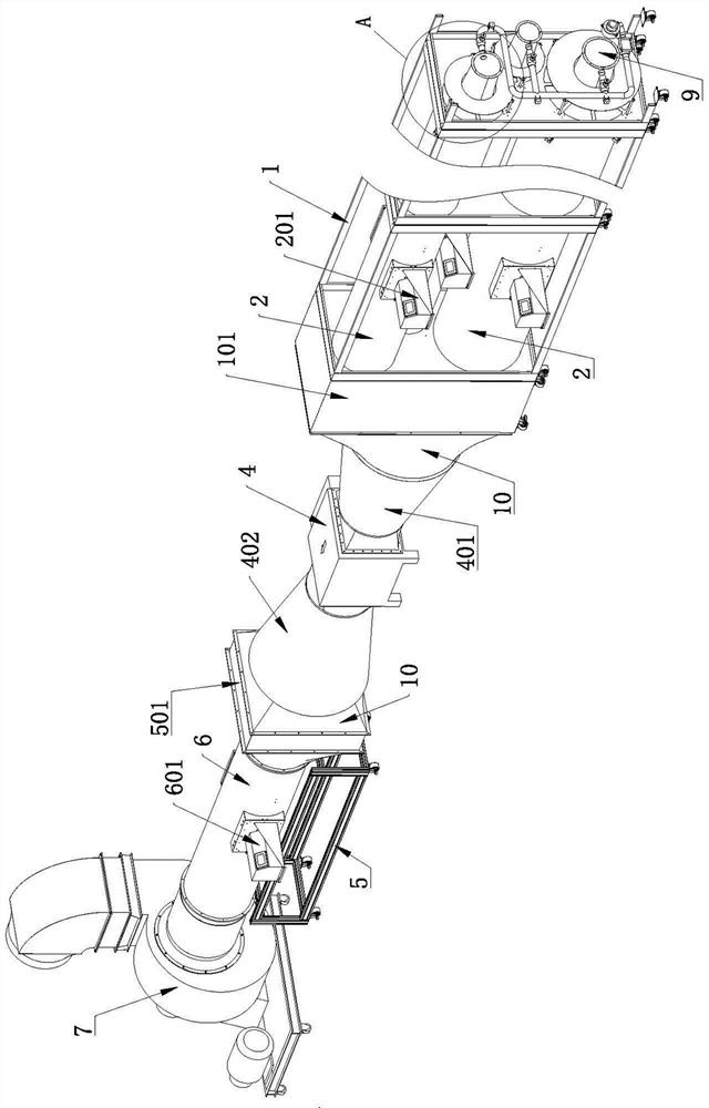
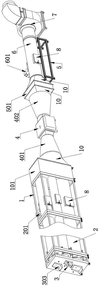
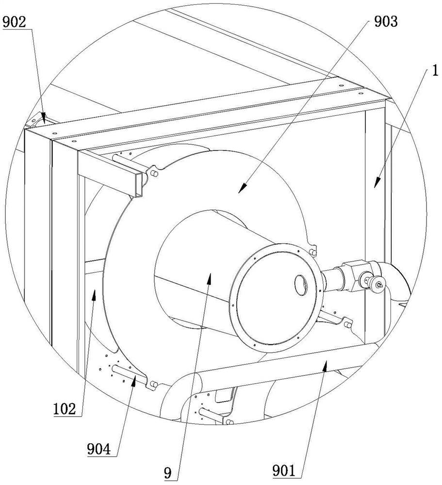
[0038] Such as figure 1 and figure 2 Commonly shown, a device for detecting purification efficiency of a lampblack purifier includes a support frame 1 on which a first oil chamber 101 is provided, and on the support frame 1 upstream of the first oil chamber 101 is provided with multiple horizontally arranged The first oil and gas delivery pipe 2 communicated with the first oil chamber 101, the diameters of multiple first oil and gas delivery pipes 2 are different; each first oil and gas delivery pipe 2 is provided with a first dust sensor 201, each The ends of the first oil and gas delivery pipe 2 are connected with the oil and gas delivery assembly 3; the first oil chamber 101 is connected with the oil fume purifier 4 through the first connecting sleeve 401, and the downstream of the oil fume purifier 4 is provided with a frame 5 , the frame 5 is provided with a second oil c...


PUM


Abstract

The invention discloses an oil smoke purifier purification efficiency detection device which comprises a supporting frame provided with a first oil chamber, a first oil gas conveying pipe communicated with the first oil chamber is arranged on the supporting frame located on the upstream of the first oil chamber, a first dust sensor is arranged on the first oil gas conveying pipe, and the first oil gas conveying pipe is further communicated with an oil sending and conveying assembly. The first oil chamber is communicated with an oil smoke purifier through a first connecting sleeve, a second oil chamber is arranged at the downstream of the oil smoke purifier, a second connecting sleeve is arranged between the oil smoke purifier and the second oil chamber, a second oil gas conveying pipe is arranged at the downstream of the second oil chamber, a second dust sensor is arranged on the second oil gas conveying pipe, and the other end of the second oil gas conveying pipe is communicated with an exhaust fan. The purification efficiency detection of a simulated field environment is realized, the oil mist conveying uniformity is high, the detection precision is guaranteed, the problems of high field arrangement difficulty and low detection precision of detection equipment are solved, and meanwhile, oil gas can be effectively prevented from adhering to the first oil gas conveying pipe and the second oil gas conveying pipe.

Description

technical field [0001] The invention belongs to the technical field of oil fume purification detection, and in particular relates to a detection device for purification efficiency of an oil fume purifier. Background technique [0002] At this stage, it is necessary to test the purification efficiency of lampblack in restaurants, canteens and other catering industries. At present, the detection work is carried out on site. For example, the patent number is: 202021955573.7, a device for testing the purification efficiency of household range hoods. A device for detecting the purification efficiency of oil fume is disclosed. The principle of the detection is to detect under the normal working environment of the equipment, but this detection method will make the oil fume particles in the sampling pipeline uneven, so the detection results are not accurate. , and the temperature of the oil will also affect the detection accuracy. At the same time, this detection cannot be applied t...

Claims


Application Information

Patent Timeline
Patent Type & Authority Applications(China)
IPC IPC(8): G01M99/00G01N15/08
CPCG01M99/005G01N15/08G01N2015/084
Inventor 施惠民施毅姜鹏飞江叶童
Owner 张家港朗亿机电设备有限公司
Learn More