Unfolding mechanism of stay wire type umbrella-shaped antenna

An umbrella-shaped antenna and deployment mechanism technology, which is applied to flexible antennas, foldable antennas, antenna supports/installation devices, etc., can solve the problems of increasing the overall weight of components, large impact force, and small torque of the umbrella deployment mechanism, and achieves The effect of preventing mutual interference, reducing weight, and large storage ratio

Pending Publication Date: 2021-10-19
SHAANXI SCI TECH UNIV
View PDF0 Cites 2 Cited by
  • Summary
  • Abstract
  • Description
  • Claims
  • Application Information

AI Technical Summary

Problems solved by technology

[0003] However, the current antenna canopy has problems such as the small torque of the canopy deployment mechanism, and the large space and weight of the connecting rod deployment mechanism. This is also the focus of relevant researchers in structural design.
In addition, the components of the umbrella-shaped antenna are basically supported by ribs, which will undoubtedly increase the overall weight of the entire component. After the umbrella-shaped antenna is deployed, it cannot control the shape of a single area, so a new umbrella-shaped antenna deployment mechanism is needed.

Method used


Image

  • Unfolding mechanism of stay wire type umbrella-shaped antenna
  • Unfolding mechanism of stay wire type umbrella-shaped antenna
  • Unfolding mechanism of stay wire type umbrella-shaped antenna

Examples


Embodiment 1

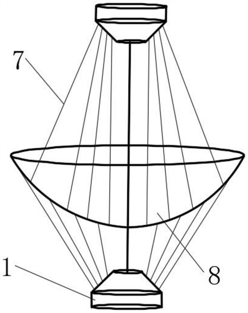
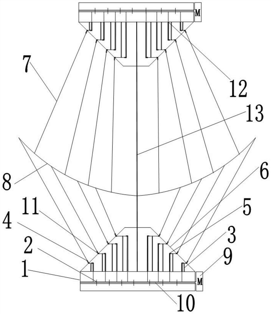
[0041] as attached figure 1 As shown, the present invention provides a deployment mechanism for a pull-wire umbrella antenna, including two pull-wire mechanisms, the two pull-wire mechanisms are respectively located on the upper and lower sides of the umbrella-shaped antenna, and each pull-wire mechanism includes a base 1 and a The boss cover 6 on the upper surface of the base 1; the upper surface of the base 1 is provided with a plurality of rows of mounting holes 12 uniformly distributed around a certain point around a certain point, and each row of mounting holes is distributed equidistantly from the center of the base 1 to the edge of the base 1. For the mounting holes, the first mounting hole 12a that is close to the center of the base 1 in each pair of mounting holes 12 is the second mounting hole 12b that is far away from the center of the base 1, and a stay wire control is fixed on each pair of mounting holes. unit.

[0042] Each pull wire control unit includes a lead...

Embodiment 2

[0046]This embodiment is based on Embodiment 1. Both the lead wire conduit 5 and the outlet port 4 are of an elbow structure, and a spring 11 is fixed inside the bending part of the elbow pipe; the other end of the tension pull wire 7 passes through the outlet port The spring 11 inside the 4, the ring 3a and the spring 11 inside the guide wire guide 5 are connected with a driving device for driving the tension pull wire 7 to be tightened or loosened.

[0047] Spring 11 is arranged in the elbow of outlet port 4 among the present invention, as Figure 5 As shown in the schematic diagram of the structure of the outlet 4 on the side of the boss base, the tension cable will pass through the ring at the free end of the spring 11. Since the spring 11 is always in a stressed state, it is ensured that the tension cable is always in a tensioned state; the spring in the lead guide 5 11 and the spring 11 in the wire outlet have the same effect, all are to allow the tension backguy to be i...

Embodiment 3

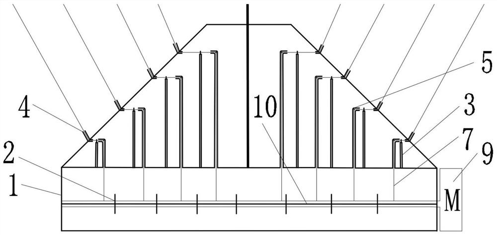
[0049] This embodiment is based on Embodiment 1. The two rows of cable control units located on the same straight line on the upper surface of the base 1 are driven by the same driving device, and each driving device includes a rotating shaft 10 and a power member 9; the rotating shafts 10 are located on the same straight line Directly below the two rows of cable control units on the top, the rotating shaft 10 is located inside the hollow base 1, the left and right sides of the rotating shaft 10 are connected to the base 1 through bearings, one end of the rotating shaft 10 is connected to the output shaft of the power part 9, and the power part 9 is fixed Outside the base 1; the lower ends of the tension pull wires 7 of the two rows of pull wire control units pass through the through holes provided on the base 1 and are wound on the side wall of the rotating shaft 10, and the power part 9 drives the rotating shaft 10 to rotate and tighten or loosen. Describe the tension guy wir...


PUM


Abstract

The invention provides an unfolding mechanism of a stay wire type umbrella-shaped antenna. The unfolding mechanism comprises two stay wire mechanisms; the two stay wire mechanisms are respectively positioned on the upper side and the lower side of the umbrella-shaped antenna; each stay wire mechanism comprises a base and a boss outer cover; a plurality of rows of stay wire control units are evenly distributed on the upper surface of the base around the circle center of the base; each stay wire control unit is provided with a lead guide pipe; the lead guide pipes and electric control push rods are fixed to the upper surface of the base side by side; a circular ring is fixed to the telescopic end of each electric control push rod; the circular rings correspond to wire outlets fixed to the boss outer cover; and the upper ends of tension stay wires are fixedly connected with the umbrella-shaped antenna, and the lower ends of the tension stay wires sequentially penetrate through the wire outlets, the circular rings and the lead guide pipes to be connected with driving devices for driving the tension stay wires to be tensioned or loosened. According to the unfolding mechanism of the stay wire type umbrella-shaped antenna, after the satellite umbrella-shaped antenna is synchronously unfolded, the umbrella cover shape of the umbrella-shaped antenna is accurately and independently controlled, so that the unfolding performance of the umbrella-shaped antenna is higher, and the storage ratio and the unfolding precision are more reliable.

Description

technical field [0001] The invention belongs to the technical field of umbrella antennas, and relates to a deployment mechanism of a pull wire umbrella antenna. Background technique [0002] With the rapid development of aerospace technology, there are higher requirements for spaceborne deployable antennas. Limited by the size of the rocket fairing during launch, in order to meet the requirements of large diameter, high storage ratio, and high precision as much as possible, the flexible umbrella-shaped deployable antenna supported by ribs, folded, and deployed to the working state has the advantages of storage ratio, surface density, and deployment. It has certain advantages in terms of performance and shape and surface maintenance in the thermal environment of space, making it widely used in the field of satellite antennas. As an important structural component of a satellite antenna, the precise control of the shape of the antenna canopy has an important impact on the sign...

Claims


Application Information

Patent Timeline
Patent Type & Authority Applications(China)
IPC IPC(8): H01Q1/16H01Q1/08H01Q1/36
CPCH01Q1/16H01Q1/085H01Q1/36
Inventor 叶伟杜鹏飞萧生
Owner SHAANXI SCI TECH UNIV
Why Eureka
Try Eureka