Atmospheric pollution control equipment
A technology of equipment and bottom plate, which is applied in the field of air pollution prevention and control equipment, can solve the problems of inconvenient air filtration treatment, inconvenient movement, inconvenience in use, etc., and achieves the effect of improving the filtering effect, improving the activity, and expanding the inhalation range.
- Summary
- Abstract
- Description
- Claims
- Application Information
AI Technical Summary
Problems solved by technology
Method used
Image

Examples
Embodiment 1
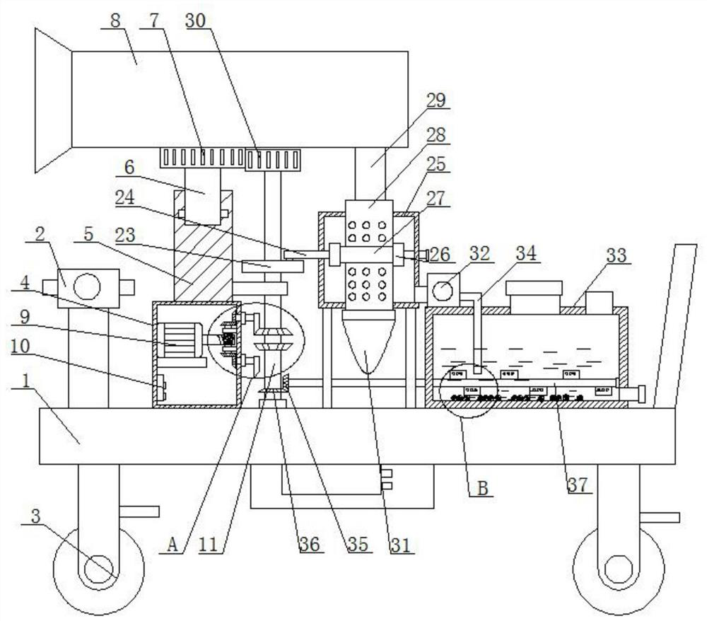
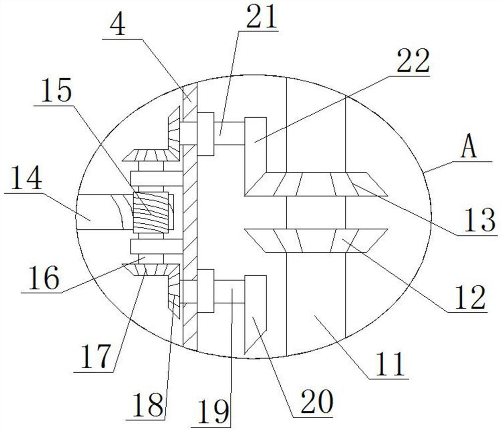
[0030] refer to Figure 1-6 , a kind of air pollution control equipment, comprising a base plate 1, a gas detector 2 is fixedly connected to the top of the base plate 1, four universal wheels 3 are fixedly connected to the bottom of the base plate 1, a fixed box 4 is fixedly connected to the top of the base plate 1, and The top of the box 4 is fixedly connected with a column 5, the top of the column 5 is rotatably connected with a rotating column 6, the top of the rotating column 6 is fixedly connected with an air suction cylinder 8, the outer fixed sleeve of the rotating column 6 is provided with a fixed gear 7, and the bottom plate 1 The top is rotatably connected with a vertical shaft 11, and the top of the vertical shaft 11 is fixedly equipped with a reciprocating gear 30, the reciprocating gear 30 meshes with the fixed gear 7, the fixed box 4 is fixedly connected with a servo motor 9 and a controller 10, and the output shaft of the servo motor 9 A reciprocating structure ...
Embodiment 2
[0039] refer to Figure 1-6 , an air pollution prevention and control device, comprising a base plate 1, the top of the base plate 1 is fixedly connected with a gas detector 2 by screws, the bottom of the base plate 1 is fixedly connected with four universal wheels 3 by screws, and the top of the base plate 1 is fixedly connected by screws There is a fixed box 4, the top of the fixed box 4 is fixedly connected with a column 5 by screws, the top of the column 5 is rotatably connected with a rotating column 6, the top of the rotating column 6 is fixedly connected with a suction cylinder 8 by screws, and the outer side of the rotating column 6 is fixed The fixed gear 7 is sleeved, the top of the bottom plate 1 is rotatably connected with a vertical shaft 11, the top of the vertical shaft 11 is fixedly installed with a reciprocating gear 30 by welding, the reciprocating gear 30 meshes with the fixed gear 7, and the fixed box 4 is fixedly connected with a The servo motor 9 and the ...
PUM
 Abstract
Description
Claims
Application Information
PatSnap Eureka turns technology decisions into work you can execute. Powered by our Innovation Knowledge Graph, it runs expert workflows across engineering, life sciences, materials and intellectual property. Get your review-ready output in minutes.


