

Translation mechanical device for machining production
A mechanical device and machining technology, applied in the direction of mechanical conveyors, mechanical equipment, transmission parts, etc., can solve the problems of blocking the inertial movement of the workpiece and trouble, and achieve the effect of easy lubrication and convenient use.
- Summary
- Abstract
- Description
- Claims
- Application Information
AI Technical Summary
Problems solved by technology
Method used
Image


Examples
Embodiment 1
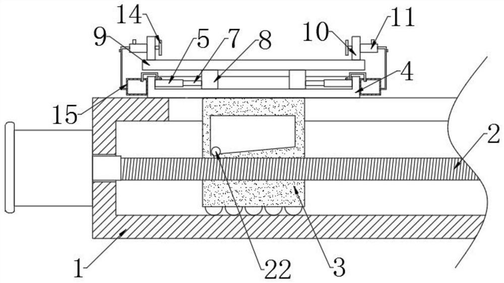
[0025] refer to Figure 1-3 , a translational mechanical device for mechanical processing production, comprising a moving base 1, a ball screw 2 driven by a motor is provided on the side of the moving base 1, a moving block 3 is threaded on the surface of the ball screw 2, and the top of the moving block 3 The surface is fixedly connected with a concave plate 4, the inner wall of the concave plate 4 is fixedly connected with a first fixed cylinder 5, the inner wall of the first fixed cylinder 5 is fixedly connected with a spring 6, and the end surface of the spring 6 is fixedly connected with a first moving rod 7, A moving plate 8 is fixedly connected to the end surface of the first moving rod 7 .
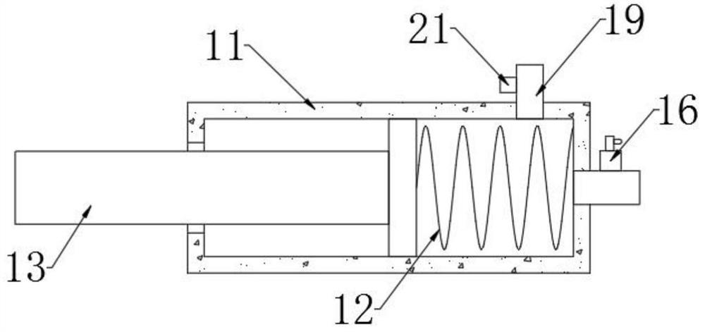
[0026] The upper surface of the moving plate 8 is fixedly connected with a placement plate 9, the upper surface of the placement plate 9 is fixedly connected with a fixed plate 10, the side of the fixed plate 10 is provided with a port, and the inner wall of the port is fixedly con...
Embodiment 2
[0032] refer to figure 1 , Figure 4 and Figure 5 , different from Embodiment 1, the inside of the moving block 3 is provided with a liquid injection chamber communicated with the threaded hole, the inner bottom wall of the liquid injection chamber is inclined upward, and the inside of the liquid injection chamber is provided with a moving ball 22, and the moving block 3 The front of the liquid storage tank 23 is fixedly connected with the liquid storage tank 23 through the infusion tube, the upper surface of the liquid storage tank 23 is provided with a liquid injection pipe, the inner wall of the liquid storage tank 23 is provided with a liquid level switch 24, and the side of the liquid storage tank 23 is provided with an indicator light 25 .
[0033] In this embodiment, when the moving block 3 stops moving, the moving ball 22 will move on the inner bottom wall of the liquid injection chamber. Under the influence of gravity, the connection between the liquid injection c...
PUM
 Abstract
Description
Claims
Application Information