Permanent magnet synchronous motor end cover connecting device

A permanent magnet synchronous motor and connecting device technology, which is applied in the direction of electromechanical devices, electrical components, electric components, etc., can solve the problems of bearing seat wear of the end cover, increase the degree of bearing wear, and inconvenient replacement of bearings, etc. Increase the sealing effect and facilitate the lubrication effect

Active Publication Date: 2022-01-11
扬州市华天电机有限公司
View PDF7 Cites 0 Cited by
  • Summary
  • Abstract
  • Description
  • Claims
  • Application Information

AI Technical Summary

Problems solved by technology

[0003] When the motor end cover is installed, the bearing is generally placed in the bearing seat of the end cover, the end cover is installed and fixed, and the shaft body at the rear end of the motor is inserted into the bearing. However, during the high-spe

Method used


Image

  • Permanent magnet synchronous motor end cover connecting device
  • Permanent magnet synchronous motor end cover connecting device
  • Permanent magnet synchronous motor end cover connecting device

Examples


Example Embodiment

[0031] In order to make the techniques, creative characteristics of the present invention, it is easy to understand that the present invention is further illustrated in connection with the specific embodiments.

[0032] In the description of the present invention, it is to be understood that the terms "upper", "lower", "front", "post", "left", "right", "top", "bottom", "inside", " The orientation or position of the instructions such as "is based on the orientation or positional relationship shown in the drawings, which is merely intended to describe the present invention and simplified description, rather than indicating or implying that the device or component must have a specific orientation. Specific orientation configurations and operations are not to be understood as limiting the invention.

[0033] In the description of the present invention, it is to be described in that, unless otherwise expressly specified and defined, the term "mount", "connected", "set" should be used t...


PUM


Abstract

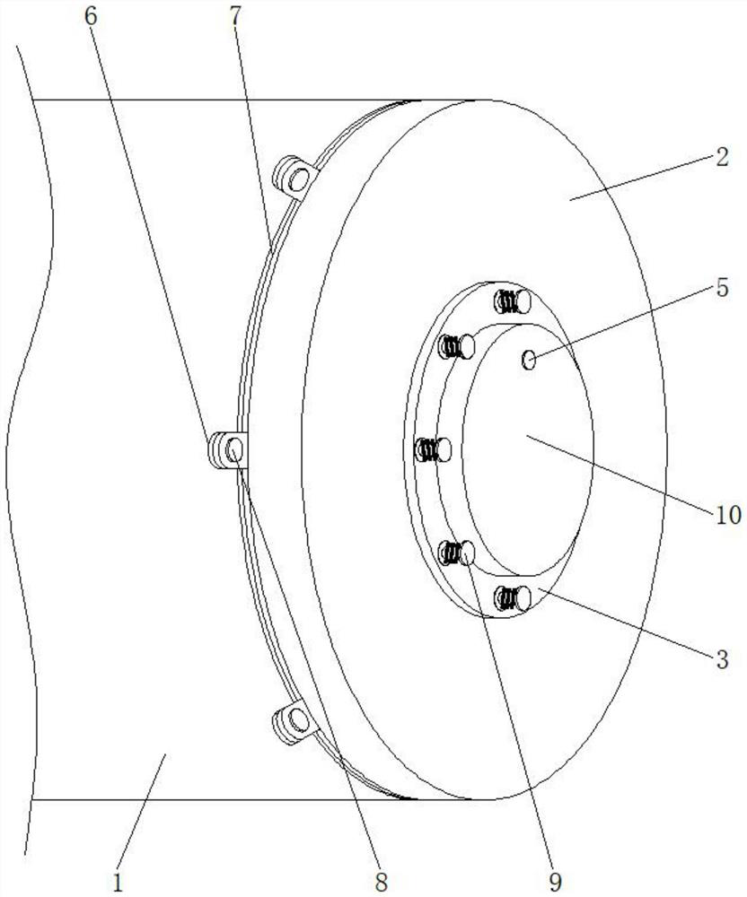
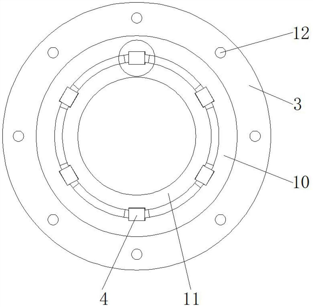
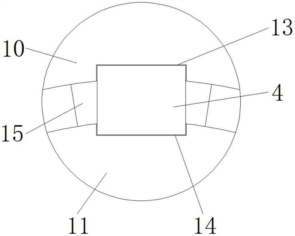
The invention relates to the technical field of permanent magnet synchronous motors, and discloses a permanent magnet synchronous motor end cover connecting device which comprises a motor body, an end cover body, a cover plate, a rubber block and a rubber plug. The end cover body covers the right side of the motor body, mounting plates are arranged around the outer ring of the right side of the motor body and the outer ring of the left side of the end cover body, the end cover body is mounted on the right side of the motor body through the mounting plates, the mounting plates are mounted through mounting bolts, a bearing hole is formed in the middle of the end cover body, and the bearing hole is communicated with the two sides of the end cover body. The bearing hole is formed in the middle of the end cover body, the cover plate is installed on the surface of the end cover body on the right side of the end cover body through the fastening bolt, the spring arranged on the outer ring of the fastening bolt in a sleeving mode can have a certain damping effect, corrosion is avoided, the bearing is convenient to disassemble and replace, and the lantern ring and the rubber block have the good damping effect so that abrasion to the tail end of the bearing can be reduced; and the end cover body is prevented from being abraded, and meanwhile, the bearing can be conveniently lubricated.

Description

technical field [0001] The invention relates to the technical field of permanent magnet synchronous motors, in particular to a permanent magnet synchronous motor end cover connection device. Background technique [0002] At present, permanent magnet synchronous motors provide excitation with permanent magnets, which makes the motor structure relatively simple, reduces processing and assembly costs, and saves the collector rings and brushes that are prone to problems, improving the reliability of motor operation; and because There is no need for excitation current and no excitation loss, which improves the efficiency and power density of the motor. The motor end cover is installed at the rear end of the motor, and one end of the motor end cover is formed with a bearing chamber boss protruding axially outward to realize the motor The fixing of the rear end bearing and the sealing of the inside of the motor. [0003] When the motor end cover is installed, the bearing is genera...

Claims


Application Information

Patent Timeline
IPC IPC(8): H02K5/04H02K5/16H02K5/24
CPCH02K5/04H02K5/24H02K5/16H02K5/163Y02T10/64
Inventor 张其朝
Owner 扬州市华天电机有限公司
Why Eureka
Try Eureka