Heat exchange structure and heat exchange integrated device and engine oil heat exchange system

A technology of heat exchange structure and engine block, which is applied in the direction of engine lubrication, engine components, machines/engines, etc. It can solve the problems that the heat exchange performance is difficult to meet the heat dissipation requirements, etc., and achieve the effect of sufficient heat exchange and improved heat exchange efficiency

Active Publication Date: 2022-07-29
ZHEJIANG YINLUN MACHINERY
View PDF4 Cites 0 Cited by
  • Summary
  • Abstract
  • Description
  • Claims
  • Application Information

AI Technical Summary

Problems solved by technology

[0006] The purpose of the present invention is to provide a heat exchange structure, a heat exchange integration device and an engine oil heat exchange system to solve the problem in the prior art that the heat exchange performance is difficult to meet the heat dissipation requirements in a small heat exchange space. Asked technical questions

Method used


Image

  • Heat exchange structure and heat exchange integrated device and engine oil heat exchange system
  • Heat exchange structure and heat exchange integrated device and engine oil heat exchange system
  • Heat exchange structure and heat exchange integrated device and engine oil heat exchange system

Examples


Embodiment

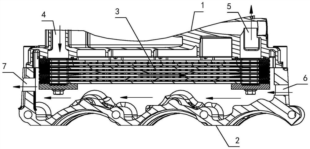
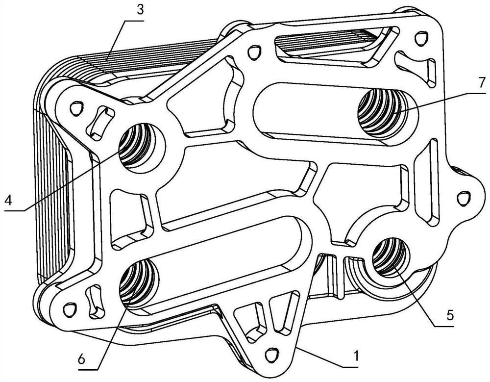
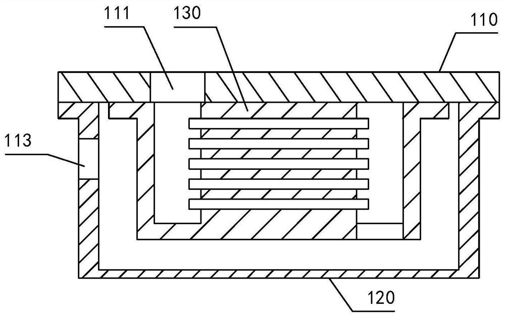
[0056] This embodiment provides a heat exchange structure, an integrated heat exchange device, and an engine oil heat exchange system. Please refer to Figure 3-1 to Figure 6-4 , Figure 3-1 to Figure 3-3 Three schematic structural diagrams of the heat exchange structure provided in this embodiment, wherein, Figure 3-1 The connection shell shown is not provided with the heat exchange outer channel outlet, Figure 3-2 and Figure 3-3 The connection shell shown is provided with a heat exchange outer channel outlet, Figure 3-3 The number of heat exchangers shown is 2. In order to facilitate the display of the structure, Figure 3-1 to Figure 3-3 Only the flow channels through which the heat exchange medium flows are shown, and the flow channels through which the raw liquid flows are not shown; Figure 3-2 The arrow direction shown is the flow direction of the heat exchange medium. Figure 4 The principle diagram of the heat exchange integrated device provided in this embo...


PUM


Abstract

A heat exchange structure, a heat exchange integrated device and an engine oil heat exchange system relate to the technical field of heat exchange. The heat exchange structure includes a heat exchange base and a heat exchanger; a closed heat exchange cavity is formed between the heat exchange base and the connecting shell; the heat exchanger is arranged in the heat exchange cavity, and the heat exchanger and the heat exchange base The heat exchanger is provided with a heat exchange inner flow channel and a raw liquid flow channel that are not connected to each other; the heat exchange base is provided with a raw liquid inlet and a raw liquid outlet that communicate with the raw liquid flow channel, and is also provided with a heat exchange inner flow channel. The heat exchange outlet is communicated; the heat exchange cavity outside the heat exchanger is the heat exchange outer flow channel; the heat exchange inner flow channel is communicated with the heat exchange outer flow channel. Both the heat exchange integrated device and the engine oil heat exchange system include a heat exchange structure. The purpose of the present invention is to provide a heat exchange structure, a heat exchange integrated device and an engine oil heat exchange system, so as to solve the problem in the prior art that the heat exchange performance in a small heat exchange space is difficult to satisfy the heat dissipation to a certain extent. requested technical issues.

Description

technical field [0001] The invention relates to the technical field of heat exchange, in particular to a heat exchange structure, a heat exchange integrated device and an engine oil heat exchange system. Background technique [0002] In the previous oil cooler design, the form of the cooler is selected according to the engine body structure and the heat dissipation performance required by the customer; the plate-fin oil cooler and the box-type oil cooler are the two types of the existing oil cooler. a common form. [0003] like figure 1 As shown, the plate-fin oil cooler (also called water bath oil cooler) is assembled in the water cavity formed by the oil cooler base 1 and the engine block 2; figure 1 The direction of the arrow in is the flow direction of coolant and oil. Among them, the cooling liquid flow mode: the cooling liquid flows into the water cavity from the water inlet 6 provided on the engine block 2, passes through the outer space of the oil cooler 3, exchan...

Claims


Application Information

Patent Timeline
Patent Type & Authority Patents(China)
IPC IPC(8): F01M5/00F28D9/00F28F9/26
CPCF01M5/002F01M5/007F28D9/0037F28F9/26
Inventor 李伟杰夏苏娥丁启乾蒋雨轩
Owner ZHEJIANG YINLUN MACHINERY
Why Eureka
Try Eureka